At one generic weld corner, a narrow brush envelope covered the complete 24.0 mm² target and kept its rigid hub 3.0 mm from the wall. A grinder centered on the same x = 8 mm axis covered the target too, but its disk and annular guard intersected the wall. Shifting the grinder axis 12 mm to x = 20 mm cleared both parts. Its projected footprint over the protected floor region nevertheless grew from 132.9 to 372.9 mm², while finite target contact became 23.1 mm².
I obtained these values from three separately staged, static cells in an AI-operated Blender 5.2.2 LTS session. They answer reach, finite-body clearance, and projected footprint questions. They do not show weld-spatter removal, coating preservation, or tool performance.
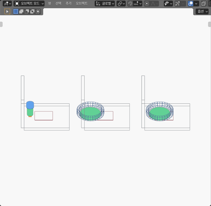
One target required three separate checks
The fixture used metres internally. Its wall occupied x = -4 to 0 mm, and the residue target ended at z = 2 mm. A red wire rectangle on the floor marked the protected region from x = 14 to 38 mm and y = -10 to 10 mm. That rectangle was an annotation for projection measurements, not another obstacle. The target top was 4 × 6 mm. The brush bundle and hub radii were 4 and 5 mm; the grinder disk radius was 14 mm, with a guard spanning radii 15–18 mm. Both tool axes were vertical. Measurements below are rounded geometric values, not manufacturing allowances.
For each cell, I recovered the evaluated working-face polygon and tested its finite overlap with the target top face. I checked the working element and rigid hub or guard against the wall and floor as separate solid pairs. I then projected the working face vertically onto the protected rectangle. This kept three questions from being collapsed into one result.
| Static cell | Working-face contact with target | Wall and floor relation | Protected-region projection |
|---|---|---|---|
| Rigid brush envelope | 24.0 mm² | Hub clears wall by 3.0 mm; working face is 2.0 mm above floor | 0 mm² |
| Grinder, same axis | 24.0 mm² | Disk and annular guard both intersect wall; working face is 2.0 mm above floor | 132.9 mm² |
| Grinder, axis at x = 20 mm | 23.1 mm² | Disk clears wall by 6.0 mm and guard by 2.0 mm; working face is 2.0 mm above floor | 372.9 mm² |
The brush reached without placing its hub in the corner
The brush cell used a closed, rigid working bundle rather than deformable bristles. Its evaluated face covered the full 24.0 mm² target. The target probe was inside that face, the bundle remained 4.0 mm from the wall, and the larger hub retained 3.0 mm of wall clearance. Its downward projection did not enter the protected rectangle.
That is a useful access result: a narrow working envelope can occupy the target pose while the wider body remains clear of the wall. It is not evidence that real bristles will bend correctly, maintain force, remove residue, or preserve a coating. Those depend on media, speed, feed, compliance, wear, and the workpiece. The geometry only establishes that this authored envelope can reach the target without a finite solid conflict.
Centering the grinder preserved contact but lost wall clearance
The centered grinder used a closed 32-sided disk and a separate 32-sided annular guard. These are generic authored shapes, not commercial CAD. On the brush axis, the disk still covered all 24.0 mm² of the target. Reach alone therefore looked acceptable.
The body check reversed that conclusion. The disk intersected the finite wall, and the guard did too. A negative support gap was recorded for the centered guard, but that number is not a penetration depth; the valid conclusion is simply that the finite solids intersected. Its projected working-face area over the protected region was 132.9 mm².
This is the same distinction that matters when checking whether a complete tool can pass through an opening, rather than checking only its centerline or tip. The whole-driver access experiment develops that broader envelope test for recessed fasteners.
Offsetting the axis fixed one conflict and enlarged another footprint
Shifting the grinder axis to x = 20 mm kept the target probe inside the disk face, but the polygonal disk boundary no longer covered the entire rectangular target. Finite contact became 23.1 mm². In exchange, the disk gained 6.0 mm of wall clearance and the annular guard gained 2.0 mm. Neither intersected the wall.
The offset did not reduce the protected-region projection. It increased it to 372.9 mm² because more of the working disk lay above the annotated rectangle. All three working lower faces remained 2.0 mm above the actual floor, so none of these projection areas is floor contact or coating damage. Projection answers where an element lies above a region; it does not say that the element touched or altered it.
The practical decision is therefore conditional. If the centered grinder conflicts with the wall, moving its axis can restore rigid-body clearance, but the new pose must be checked again for target coverage and nearby protected regions. The tool-side compliance direction experiment addresses a different part of that setup: whether an allowed slide direction supplies the required normal correction.
Geometry ends before cleanup quality begins
FerRobotics presents powered brushing as one method for weld-spatter removal and separately shows force-controlled grinding for weld leveling. Those are manufacturer application claims. I used them only to motivate comparing a brush envelope with a grinder disk and guard; no FerRobotics product geometry or process result was reproduced here. The application page was checked on October 8, 2026.
Before choosing a real process, keep the checks in order: confirm that the working face reaches the intended residue, test the complete rigid tool against the corner, and evaluate protected-region exposure in the selected pose. Then validate the real media, force, speed, feed, heat, wear, finish, and safety constraints. A static Blender clearance result can reject a bad geometric arrangement, but it cannot approve the cleanup process.