Two corrected cells in my Blender experiment placed the tool-face centre at approximately [12, 0, 2] mm and covered the same 24.0 mm² target. Their upstream clearance was different. Moving only the carriage and head left the upstream body about 2.0 mm from a fixed guard. Moving the whole tool assembly to the same endpoint created an 880.0 mm³ finite-solid intersection between that body and the guard.
This was an AI-operated Blender 5.2.2 LTS concept model with three separately authored static cells. It tested a mechanical layout decision: which rigid members share a correction. It did not execute a robot, slide, force loop, controller, or physical tool.
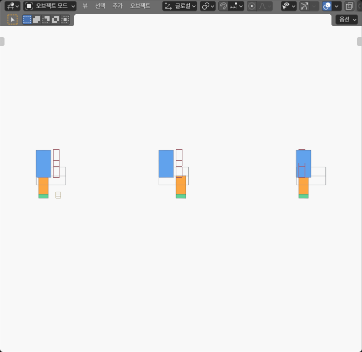
Same endpoint did not mean the same clearance
The baseline head did not reach the target. In each corrected cell, the head was placed 12 mm farther along +X, its lower face normal remained along -Z, and all four face corners matched between the two corrected endpoints within the numerical comparison allowance. Both corrected faces covered the target fully.
The difference was membership. The local case translated only the carriage and head. The whole-tool case translated the upstream body, guide, carriage, and head together. The fixed target and guard stayed in the same cell-relative positions.
| Static cell | Members translated +12 mm | Tool-face contact | Upstream body versus fixed guard |
|---|---|---|---|
| Baseline | None | 0 mm² | Disjoint; 2.0 mm finite gap |
| Local carriage correction | Carriage and head | 24.0 mm² | Disjoint; 2.0 mm finite gap |
| Whole-tool correction | Body, guide, carriage and head | 24.0 mm² | Positive-volume intersection: 880.0 mm³ |
The intersection volume describes the common volume of two authored boxes. It is not a penetration depth, contact force, deformation, damage, or safety margin.
Six finite boxes make the comparison reproducible
All dimensions were generic and expressed in millimetres. The upstream body spanned x = -6 to 6, y = -8 to 8, and z = 24 to 40. The guide spanned x = -6 to 18, y = -7 to 7, and z = 16 to 24. The carriage occupied x = -4 to 4, y = -6 to 6, and z = 6 to 16; the head used the same x-y range and z = 2 to 6.
The target occupied x = 10 to 14, y = -3 to 3, and z = 0 to 2. The fixed guard occupied x = 8 to 13, y = -12 to 12, and z = 27 to 38. Each display cell used the same six closed-box shapes with its declared pose offsets. I entered metre equivalents in Blender. Display-cell origins were at x = -100, 0 and +100 mm; those offsets were removed before comparing the local geometry.
The geometry audit reconstructed all 144 evaluated vertices from 18 closed boxes. It recovered every part displacement, the head’s lower face, the target’s upper face, and the finite body-guard relation. The guide and carriage retained 96.0 mm² of coplanar finite-face contact in every cell. The analysis used a 4 µm coordinate allowance and an 8 µm two-solid comparison allowance for numerical consistency; these are not manufacturing tolerances or evidence of hardware accuracy. The contact result confirms the authored face relation only; it does not prove a slide joint, attachment, load path, friction, or force transfer.
Local correction preserved the upstream envelope
In the local cell, I placed the carriage and head 12 mm to the right while retaining the baseline positions of the upstream body and guide. The head centre changed from approximately x = 0 to x = 12 mm between the authored cells, and its lower face covered the complete 24.0 mm² target. Meanwhile, the upstream body retained essentially the same 2.0 mm Euclidean finite-face clearance from the guard as in the baseline.
That is the useful mechanical observation: a local correction can change the working endpoint without translating every upstream solid through nearby structure. It is not a universal argument for a local stage. If the guard were placed around the carriage or head instead, the local case could become the limiting layout.
Our earlier compliance-slide experiment answers a separate question: whether an allowed guide direction provides enough correction along a contact normal. Here the direction and magnitude were fixed; only the moved membership changed.
Whole-assembly correction changed the upstream relation
In the whole-tool cell, all four mechanism members received the same +12 mm translation. The head again reached the target, with a measured contact area of 23.999959 mm² rather than 24.000004 mm² in the local cell. That tiny difference is floating-point geometry within the declared numerical allowance, not a different physical result.
The upstream body also moved 12 mm, so its x interval shifted into the fixed guard. The independently recovered common volume was 879.999 mm³, rounded to 880.0 mm³ in the table. The endpoint succeeded at the head while failing the authored body-clearance condition.
This complements the whole-driver access experiment, which checks whether a complete fixed tool envelope fits through a service opening. The present comparison asks which members belong to the moving envelope in the first place.
Use moved membership as an early layout test
PushCorp’s force-compliance overview, checked on October 8, 2026, describes a sliding carriage and a closed-loop architecture that operates independently of robot-arm motion. That manufacturer description motivates separating local carriage motion from upstream movement. It does not validate this generic geometry or establish accuracy, force performance, or superiority over arm control.
For a new layout, define the required tool-face correction in one frame, list every rigid member that shares it, and place nearby guards, fixtures, cables, and covers in the same model. Verify that competing designs reach the same endpoint, then check each moved body against fixed geometry. Change the guard placement, correction distance, stroke, and membership deliberately and repeat the finite checks.
These three cells were static endpoints, not a recorded motion history. They do not establish continuous-path clearance, stiffness, friction, mass dynamics, bandwidth, force regulation, controller behavior, attachment strength, hardware accuracy, product compatibility, or safety. Their value is narrower: successful endpoint reach cannot stand in for clearance of the assembly that moved to create it.