A bayonet coupling needs two different geometric checks in the right order. The lugs must first pass through the entry windows, and only after the male part is seated deeply enough should a turn place those lugs beneath the retaining shelves. In Physical AI Lab’s AI-assisted Blender 5.2.2 LTS experiment, the deeply seated, 60-degree state combined about 12.29 mm² of projected shelf overlap per lug with a 0.50 mm axial gap and no solid intersection. Applying the same turn at a shallower axial position produced the same projected overlap, yet the finite solids intersected. The practical lesson is simple: a favorable top-view overlap does not certify an assemblable retained state.
This was a generic static geometry study, not a reproduction of a commercial coupling. Its purpose was to separate entry clearance, seating depth, rotational overlap, and three-dimensional interference so that each can become an explicit design check.
Why entry alignment answers only the first question
The male group used a 24-sided plug with a 9 mm nominal radius and two opposed rectangular lugs. Each lug extended from 8 to 13 mm from the center, was 4 mm wide, and was 2 mm thick. The connected female group used an annular shelf from 10 to 15 mm radius, interrupted by two 30-degree entry windows at opposite sides. The shelf occupied Z = 0 to 3 mm. An outer rim from 14 to 15 mm radius, with the same 3 mm thickness, completed the collar. The plug extended 10 mm on either side of the lug mid-plane. These dimensions describe the faceted model; the bore was not replaced with a smooth circle.
At zero degrees, the lugs lined up with the windows. In the inserted state, the closest window-side relation had about 0.59 mm of planar edge clearance. The corresponding finite three-dimensional side-face distance was about 0.77 mm because the closest features were also separated axially. At that state, the lug’s upper face also sat 0.50 mm below the shelf’s lower plane. This axial offset does not measure a contact gap where the lug has no shelf projection. Those values describe different geometric relationships; combining them into one informal “clearance” number would hide which surface needs revision.
The industrial reason to care about state order is not unique to this model. A 2020 Primetals description of automated casting, checked on October 9, 2026, describes adjustable bayonet clamping that follows slide-gate movement, together with vision-based positioning. I use that only as motivation for treating position and clamping state separately. The page does not supply the dimensions, lug geometry, turn angle, or performance evidence used here.
Four static states exposed the failed assumption
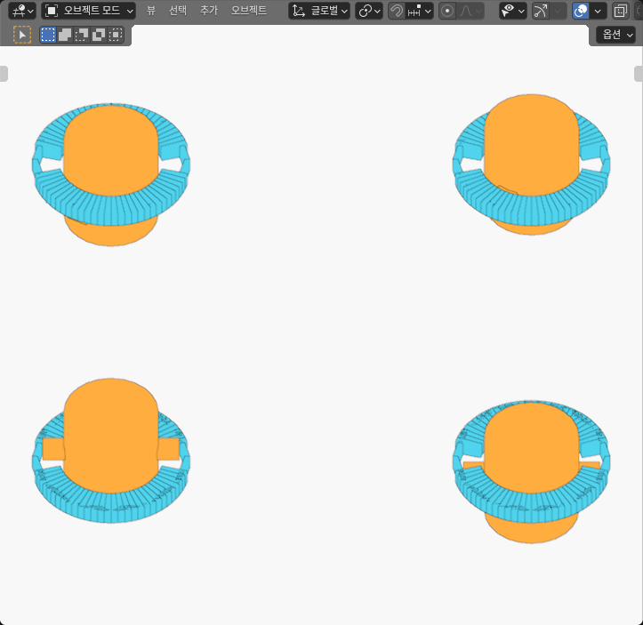
I authored four independent cells in a common coordinate system. Each listed Z position identifies the lug mid-plane relative to the shelf’s lower face. That plane was placed at +5 mm and zero degrees for entry_above, then at -1.5 mm and zero degrees for inserted_open. The two turned cells used 60 degrees: retained_deep kept the -1.5 mm axial position, while shallow_turned moved the male part to +1.5 mm.
| State | Male position | Clocking | Measured finite relation | Design reading |
|---|---|---|---|---|
| Entry above | Z = +5.0 mm | 0° | All cross-component solids disjoint; closest bound about 1.00 mm | Aligned above the windows, but insertion was not simulated |
| Inserted open | Z = -1.5 mm | 0° | About 0.59 mm planar edge gap and 0.77 mm finite 3D side-face distance | The lugs clear the authored entry geometry in this static state |
| Retained deep | Z = -1.5 mm | 60° | 12.29 mm² projected shelf overlap per lug; 0.50 mm axial gap; solids disjoint | Overlap and axial order agree in the tested retained state |
| Shallow turned | Z = +1.5 mm | 60° | Same 12.29 mm² projected overlap, but 12 strict interior pair intersections | The top view looks favorable while the 3D placement is impossible |
The comparison that mattered was between the two turned states. Their projected lug-on-shelf areas were effectively the same, but their axial relationships were opposite. The deep state left half a millimetre between the relevant faces. The shallow state placed the solids through one another with 2 mm of axial overlap. Projected overlap was therefore necessary for the intended retained relationship in this model, but it was not sufficient to establish a valid assembly.
I measured finite faces, not only centerlines
For each state, I evaluated the transformed corners and faces of both rigid groups in the same frame. I checked every male-to-female solid pair for strict separation or common interior. I then calculated the entry-window edge distance, the full 3D face distance, the lug projection onto the shelf, and the axial face order as separate quantities.
That separation prevents two common mistakes. First, a plan-view gap can be smaller than the shortest 3D distance because the finite faces sit at different heights. Second, two shapes can overlap in projection while remaining separated, touching within the numerical band, or intersecting in 3D. The reported 12.29 mm² is a shelf-only projected area for each lug. It does not measure loaded contact area or establish strength or a pull-out rating.
The coordinate consistency check used a 4 micrometre allowance; relation checks used an 8 micrometre comparison band. Reported measurements are rounded for reading. Those values were numerical consistency bounds for this authored model. They are not machining tolerances or evidence of physical accuracy.
Choose the axial seat before choosing the turn
A useful design sequence starts with an explicit seated Z position. At that depth, test the unturned lugs against the complete finite windows. Next, rotate the same rigid male group and require both a declared projected shelf overlap and disjoint three-dimensional solids. Keep those results separate in the design record: window margin, side-face distance, axial face gap, and projected retained area answer different questions.
If entry is too tight, widening a window may increase the entry margin, but removing shelf material can also reduce the retained overlap. Broadening a lug can move the tradeoff in the other direction: more possible shelf projection, less window margin. Neither modification was tested here. The point is to rerun both states after changing either feature instead of optimizing one screenshot or one scalar.
This complements the tool-changer port-clocking experiment, which separated mechanical fit from circuit identity. It also differs from the dovetail end-loading experiment, where the central question was linear access into a finite groove. A bayonet adds an ordered axial-then-rotational relationship and therefore needs both an entry check and a retained-state check.
What this experiment still does not establish
The four cells were independently authored snapshots. They do not prove that a continuous insertion-and-turn path stays clear between the samples. A next check should sweep the complete finite lugs through the intended axial and rotational schedule, including transition timing, tolerances, and any lead-in surfaces. That path study should occur before treating the static retained state as assemblable.
The model also omitted deformation, contact response, friction, clamp force, seals, pull-out load, wear, manufacturing variation, sensing, and robot execution. The attached lugs and connected collar pieces were geometric rigid groups, not vendor CAD or tested hardware. Within those limits, the experiment did answer a useful design question: seat depth must be established before the turn, because entry clearance and projected shelf overlap can both look acceptable while the full solids still occupy the same space.