Robot position, velocity and torque control are not three interchangeable labels for the same command. Position control asks a joint to reach an angle, velocity control asks it to maintain a rate, and torque or effort control asks the drive to create a turning effect. The available command interface and the feedback closed below it determine the real behavior.
Most servo joints use cascaded loops. A fast current loop regulates motor torque, a slower velocity loop surrounds it, and a position loop may surround both. Gear ratio, friction, backlash, compliance, sensors, saturation and thermal limits change what reaches the output axis.
Use this guide with the robot encoder guide and contact-control comparison. Gains and mode transitions must be validated on the actual drive, mechanism and load; a software interface name alone does not prove output torque or safety.
Start with the quantity that the application must regulate
A pick-and-place axis usually prioritizes path position and timing. A conveyor or wheel may prioritize speed. Contact, force limiting or dynamic balance may need torque-level behavior. Translate the task into tracking error, disturbance rejection, contact response and stop requirements before choosing the command mode.
The outer application can still generate several quantities. A trajectory may contain position, velocity and acceleration feedforward, while the joint closes an effort loop. State the commanded variable, measured variable, controller location and rate so that the architecture is unambiguous.

The current loop is the practical torque-producing layer
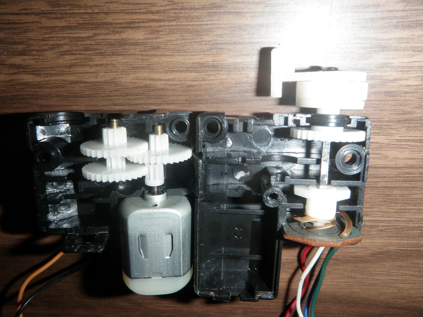
Motor torque is approximately related to q-axis current through the motor torque constant within modeled limits. The drive measures phase current and switches voltage rapidly to make current follow its reference. Electrical delay, voltage limit, current-sensor error and temperature limit bound the response.
A current command is not automatically equal to joint torque. Gear ratio, efficiency, friction, cable forces, reflected inertia and calibration intervene. If output torque matters, validate the relationship with an external force or torque reference across direction, speed and temperature.
| Command layer | Typical feedback | Output of the loop | Primary limitation |
|---|---|---|---|
| Current or torque | Motor current, sometimes torque sensor | Voltage or current demand | Voltage, current and thermal limits |
| Velocity | Encoder velocity | Torque-producing demand | Noise, delay and acceleration limit |
| Position | Encoder position | Velocity or torque demand | Compliance, backlash and path limits |
| Cartesian motion | Robot kinematics | Joint references | Singularity and model error |
| Contact objective | Force or tactile sensing | Motion or torque correction | Stability and safety limits |
The velocity loop converts speed error into torque demand
Velocity control compares measured joint or motor speed with a reference and normally produces a torque or current command. It rejects load disturbances without forcing a particular final position. Speed estimation quality matters because encoder differentiation amplifies quantization and noise.
Tune the loop with the mechanism attached. A gain that is stable on an unloaded motor may excite gearbox compliance or structural resonance after installation. Acceleration, jerk and current limits must be coordinated so the velocity controller does not remain saturated during every transition.
The position loop generates motion from angular error
Position control compares target and measured angle, then produces a velocity or torque demand. It is intuitive for trajectory execution, but high proportional gain is not free accuracy. Compliance, backlash, sensor placement and saturation can create oscillation or large contact force.
The ROS 2 Joint Trajectory Controller documentation distinguishes position, velocity and effort command interfaces and describes how trajectory error can be mapped through PID for velocity or effort commands. The hardware implementation below the interface still defines the physical behavior.
Loop bandwidth should decrease from the inside outward
The current loop must normally settle faster than the velocity loop, and the velocity loop faster than the position loop. This separation allows each outer loop to treat the inner response as approximately immediate over its own bandwidth. Poor separation creates interaction and difficult tuning.
Do not choose rates from a slogan such as ten times faster without measuring delay, resonance and computation jitter. Identify the plant response, set conservative bandwidth below problematic modes, and check gain and phase margin under payload and temperature variation.
Position, velocity and effort interfaces have different semantics
ROS 2 control exposes joint state and command interfaces for position, velocity and effort, while joint kinematics and transmission mappings connect actuator and joint spaces. An effort number may represent motor torque, joint torque or a normalized demand depending on the hardware plugin.
Document units, sign, reference frame, gear mapping, saturation and whether gravity or friction compensation is included. Confirm what happens when commands stop arriving. A simulator that applies effort directly is not evidence that a physical drive provides calibrated joint torque.
| Verification test | Position mode evidence | Velocity mode evidence | Torque mode evidence |
|---|---|---|---|
| Step or trajectory | Settling and path error | Rate tracking | Torque rise and limit |
| Load disturbance | Position recovery | Speed recovery | Torque regulation |
| Reversal | Backlash and hysteresis | Zero-crossing behavior | Friction compensation |
| Contact | Peak force and deflection | Speed-to-force transient | Force or impedance response |
| Mode transition | No position jump | No rate jump | No torque impulse |
PID terms solve different error patterns
Proportional action responds to present error, integral action removes persistent bias, and derivative or velocity feedback adds damping. Feedforward terms can supply expected gravity, inertia, velocity or friction demand so feedback corrects residual error instead of carrying the whole task.
Integral action needs particular care near saturation and mode changes. A large stored integrator can command an unexpected surge after the limit clears. Use anti-windup, bounded integrators, bumpless initialization and logged term contributions during commissioning.
Saturation and mechanics break the ideal cascade
Voltage, current, velocity, acceleration and travel limits can each clip a command. The outer loop must know when the inner loop cannot comply; otherwise error accumulates while the actuator remains pinned. Limit management should produce a controlled response rather than a hidden discontinuity.
Gearbox elasticity, backlash, stiction and structural modes mean motor-side feedback is not always output-side motion. Add output sensing or model compensation only after measuring the effect. Aggressive gains used to hide mechanical error can increase heat, wear and contact severity.
Validate tracking, disturbances and contact separately
Trajectory tracking measures path and timing error under representative speed, acceleration and payload. Disturbance tests apply known load changes and observe recovery. Contact tests introduce controlled environment stiffness and measure force, deflection and stability. One successful test does not substitute for the others.
Log references, measured states, controller terms, saturation flags, temperatures and safety events on a common time base. Repeat across direction, pose and warm-up. A repeatable output-side measurement is more useful than a clean internal command trace.
Mode transitions are part of the control design
Switching from position to torque control can create a jump if the new controller starts with a reference inconsistent with the current state. Initialize position targets, integrators and torque bias from measured conditions, and ramp authority under explicit transition logic.
Define permitted transitions, guard conditions, timeout behavior and fallback mode. Test stale commands, sensor loss, drive faults and emergency stops. A smooth nominal handoff is incomplete until the fault paths are also bounded.
- Name the regulated quantity and where feedback closes.
- Keep inner loops faster than outer loops with measured margin.
- Document command units, mappings and saturation.
- Test tracking, disturbance rejection and contact separately.
- Make every mode transition explicit and bumpless.
Frequently asked questions
Does a position-controlled robot have no torque control?
Usually it still has a fast motor-current or torque-producing loop underneath the position loop; the user may simply not command it directly.
Is a faster controller update rate always better?
No. Sampling must support the desired bandwidth, but delay, noise, jitter, computation and mechanical resonance still limit useful gain.
Is an effort command equal to measured joint torque?
Not necessarily. Confirm the hardware definition, transmission mapping, friction compensation and calibration with output-side evidence.
Will higher position gain always improve accuracy?
No. It can reduce low-frequency error but also excite compliance, increase contact force, saturate the drive and add heat.
Can the controller switch directly from position to torque mode?
Only with a designed transition that initializes references and states, limits command change and verifies fault behavior.
Joint Control Boundary Note
Control gains, limits and mode transitions are specific to the actuator, drive, sensing, load and safety design. Validate output behavior with representative hardware and do not infer calibrated torque or a safety function from a software interface name.