A series elastic actuator places an intentional elastic element in the force path and usually estimates output force or torque from its deflection. A quasi-direct-drive actuator uses a relatively large torque-dense motor with low reduction to reduce reflected inertia and passive resistance. Both can support compliant interaction, but by different physical mechanisms.
SEA and QDD are architecture families, not single performance levels. Spring stiffness, sensor resolution, ratio, motor inertia, current control, structure and thermal design determine the actual force bandwidth, transparency, impact tolerance and efficiency.
Use this comparison with the joint backdrivability guide and contact-control guide. Select by measured task performance rather than assuming that one family is always softer or faster.
SEA adds a measured spring while QDD lowers reduction
An SEA commonly consists of motor, transmission, spring, load and sensors. Spring deflection multiplied by calibrated stiffness estimates force or torque. The compliance filters impacts and decouples some gearbox disturbance from the load.
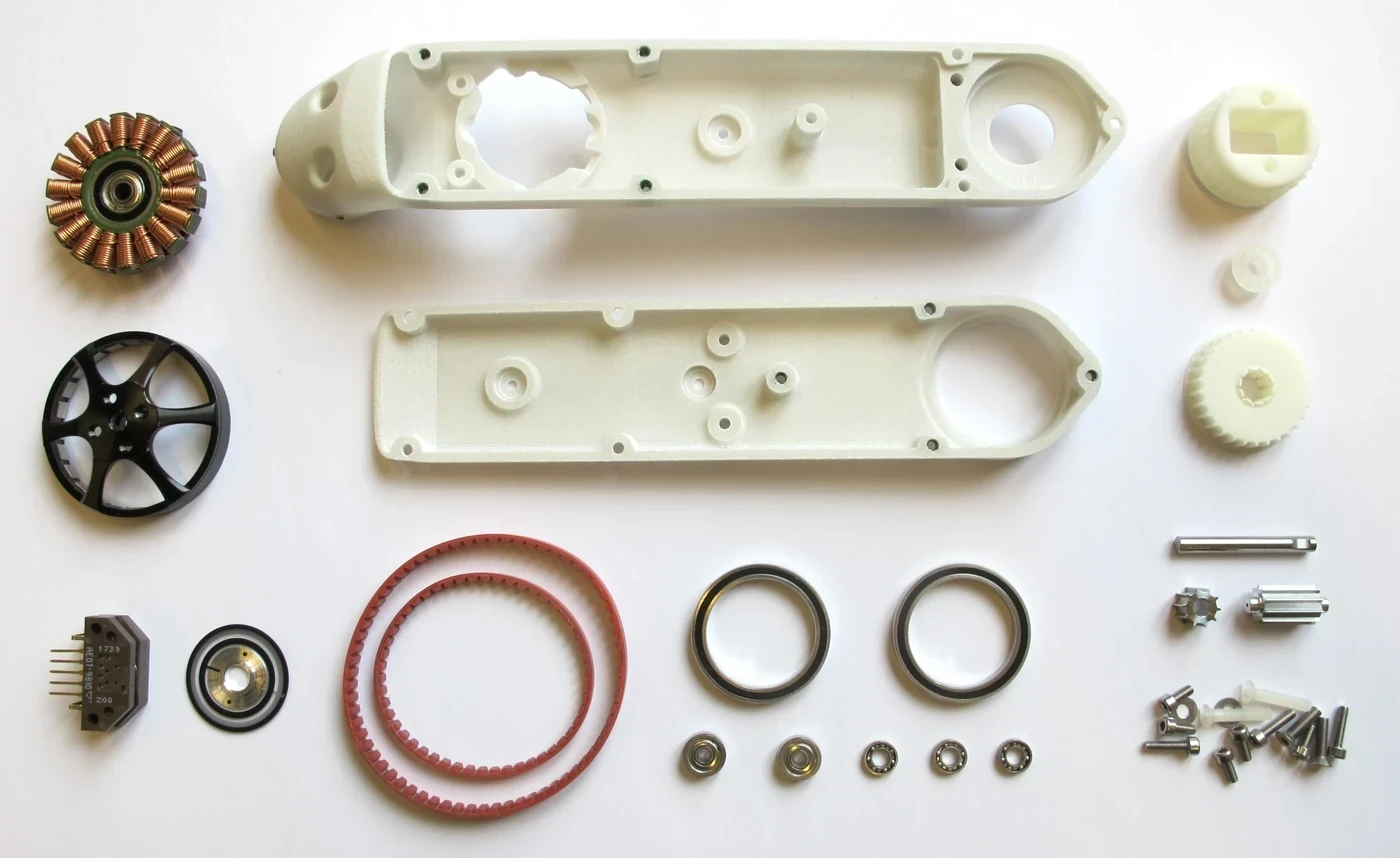
A QDD actuator moves toward direct drive by lowering the ratio while retaining some reduction. A larger motor supplies the required torque. It relies on low passive resistance and current or torque estimation rather than a mandatory series spring.
The two force paths create different design variables
SEA performance depends strongly on spring stiffness, travel, hysteresis, deflection-sensor resolution and placement. A softer spring increases passive compliance and measurable deflection but can reduce position stiffness and force-control bandwidth.
QDD performance depends strongly on motor torque density, rotor inertia, cogging, low-ratio transmission efficiency and current calibration. Low ratio improves transparency but increases motor and drive burden for the same output torque.
| Dimension | Series elastic actuator | Quasi-direct drive | Verification |
|---|---|---|---|
| Intentional element | Series spring | No required series spring | Force path inspection |
| Torque estimate | Spring deflection times stiffness | Motor current or output sensor | Reference torque test |
| Passive compliance | Defined by spring and structure | Defined by mechanics and ratio | Static load-deflection |
| Force bandwidth | Limited by spring-load dynamics and control | Limited by motor, drive and mechanics | Sine sweep |
| Impact response | Spring stores and filters energy | Low inertia and resistance pass motion | Impact test |
Spring deflection gives SEA a direct force signal
For an approximately linear elastic element, output torque can be estimated from angular deflection times torsional stiffness. Real springs show calibration error, hysteresis, temperature dependence, cross-load and structural compliance outside the sensing path.
Calibrate the assembled spring and sensor across direction and temperature. Keep deflection within mechanical travel. A stiff spring produces small signals that challenge resolution; a soft spring can bottom out or reduce motion authority.
QDD pursues transparency through low ratio
The QDD hip-exoskeleton paper describes quasi-direct drive as a high-torque-density motor with low-ratio gearing and evaluates torque, backdrive torque, bandwidth and tracking accuracy. Those measured outputs are the useful comparison dimensions.
QDD is not direct drive and not frictionless. Belts, gears, bearings, seals, motor cogging and current error remain. The motor and inverter must handle high current, so continuous torque can be thermally demanding.
Passive compliance and backdrivability are not interchangeable
An SEA can deform under load even if its upstream gearbox is not easily backdriven. A QDD joint can be easy to move but relatively stiff under a static load. Their contact response differs across frequency and controller state.
Define desired low-frequency stiffness, high-frequency impact response and powered transparency. Test with control enabled and disabled. A spring can protect against some impacts, but it does not eliminate travel stops or structural shock.
Bandwidth depends on the full plant and sensor path
SEA force control must command motor motion that changes spring deflection while the load moves. Resonances among motor inertia, spring and load set limits. QDD can achieve high torque bandwidth with a fast current loop, but motor electrical time constants, bus voltage and structure still constrain it.
Measure closed-loop force or torque frequency response with representative load. Report amplitude and phase, not only a single cutoff. Repeat near saturation and at different joint positions because load inertia and contact stiffness change the plant.
| Test | SEA focus | QDD focus | Common output |
|---|---|---|---|
| Static torque | Spring calibration and travel | Current-to-output calibration | Error and hysteresis |
| Sine sweep | Elastic resonance and phase | Current loop and structure | Bandwidth |
| Backdrive | Gear friction plus spring behavior | Ratio, inertia and friction | Torque-speed curve |
| Impact | Spring energy and end stop | Reflected inertia and peak current | Peak force |
| Thermal duty | Motor motion and gearbox losses | High motor current and cooling | Continuous torque |
Force accuracy comes from different sensors and models
SEA obtains a mechanically related torque signal when spring stiffness is known. QDD often estimates output torque from current, gear ratio and efficiency; friction and cogging create low-torque error. Either architecture can add an output torque sensor.
Compare zero, gain, hysteresis, noise and dynamic delay against the same external reference. High numerical resolution is not enough if unmeasured friction lies between sensor and output.
Impact tolerance is not a license to omit limits
A series spring can store energy and reduce the rate at which an impact reaches the gearbox. A QDD actuator’s low reflected inertia can allow the joint to yield. Both can still reach mechanical stops, exceed motor speed or produce hazardous forces under active control.
Define allowable spring deflection, motor speed, joint travel and torque. Monitor saturation and energy. Add bumpers, clutches or structural limits where the task requires them. Validate repeated impacts because fatigue and heat accumulate.
Different robot joints may justify different architectures
A leg joint may prioritize impact robustness and force bandwidth, an arm may prioritize transparency and reach, and a gripper may prioritize compact force sensing. Motor placement and cooling also vary across a robot.
Do not standardize one actuator before mapping joint-specific torque-speed and interaction needs. A mixed architecture can reduce mass and complexity if the control and maintenance system can support it.
Select with one common interaction benchmark
Create an output-side test covering static torque error, sine-wave tracking, backdrive resistance, impact peak, position stiffness, continuous thermal duty and fault-state behavior. Use the same load and measurement definitions for both candidates.
Rank the architecture after packaging, electronics, sensing, service and lifecycle are included. The better actuator is the one that meets the task envelope with margin and credible manufacturing repeatability.
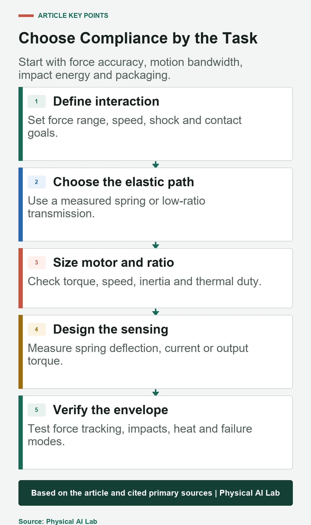
- Define force, motion and impact requirements first.
- Calibrate SEA spring deflection or QDD current-to-torque.
- Compare bandwidth and backdrive on the same load.
- Test mechanical stops, saturation and power loss.
- Allow different joints to choose different architectures.
Frequently asked questions
Is every SEA slow because it contains a spring?
No. Spring stiffness, inertia, sensors and controller determine bandwidth, though the elastic dynamics create important limits.
Does QDD have no compliance?
No. Motor, belts, gears, bearings and structure have compliance; QDD simply does not require an intentional series spring.
Which architecture has better force accuracy?
It depends on spring calibration, current and friction estimation, sensor placement and bandwidth. Measure both against an output reference.
Which is best for humanoid legs?
The answer depends on torque-speed duty, impacts, mass, package, cooling and control; different joints may choose differently.
What is the most useful comparison test?
An output force or torque sweep with representative load, combined with backdrive, impact and thermal-duty tests.
Architecture Selection Note
SEA and QDD labels do not specify force bandwidth, transparency or safety. Compare the complete actuator under common output-side tests, including controller-disabled behavior, saturation, mechanical travel, thermal duty and impacts.