Robot joint backdrivability is the ability of an external output torque to move the transmission and motor backward. A highly backdrivable joint requires little output torque to start and sustain motion. The result depends on gear ratio, friction, reflected inertia, motor cogging, speed and electrical state.
Backdrivability is not identical to compliance or safe interaction. A rigid mechanism can be easy to backdrive, and an elastic mechanism can resist slow motion. Active torque or impedance control can make a joint feel compliant while power and sensors work, but passive behavior remains important during impacts and faults.
Use this guide with the impedance and admittance guide and torque-density guide. Compare joints only with a common output-side test and electrical condition.
Backdrivability begins with externally driven output motion
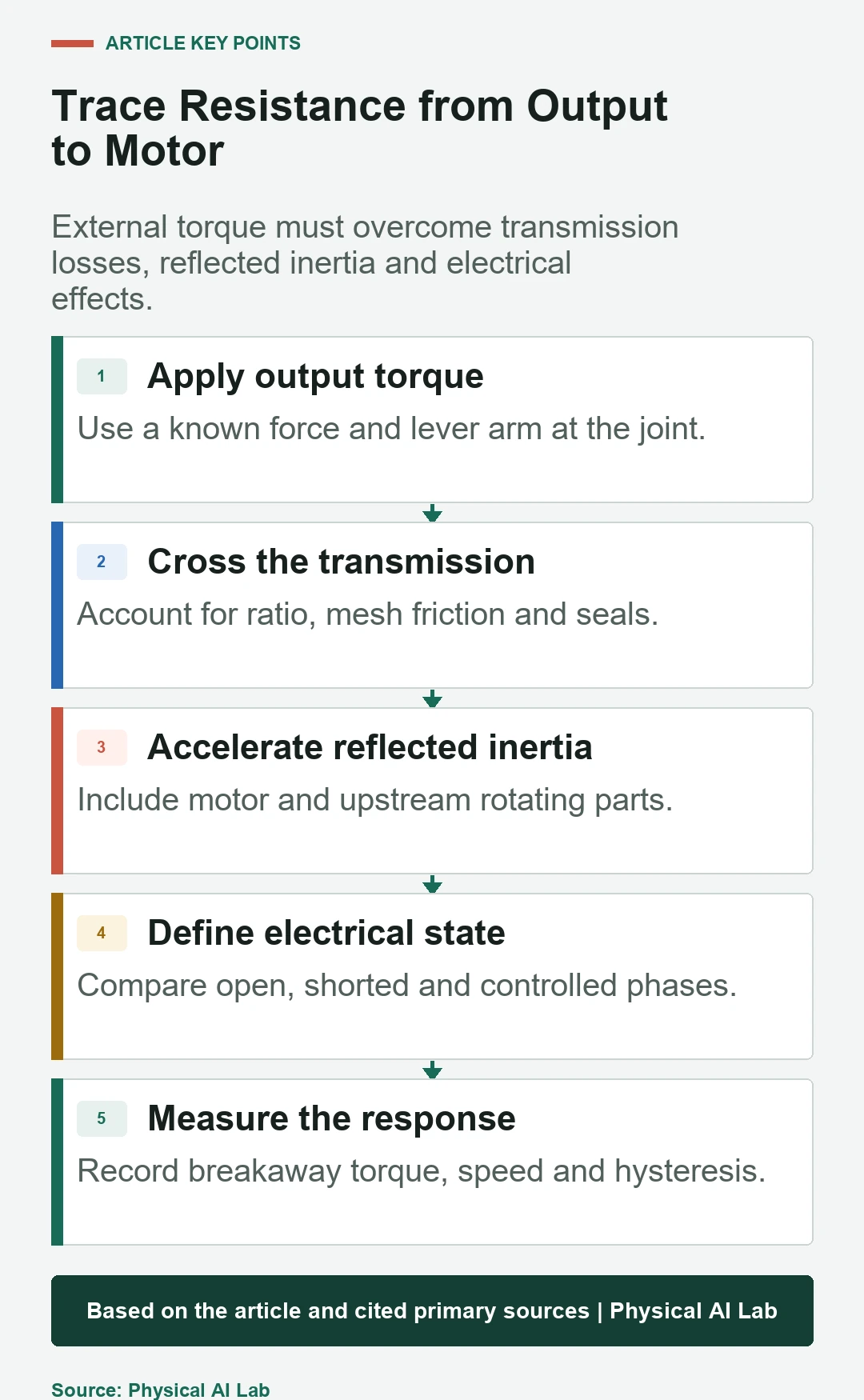
Apply torque at the joint output and observe whether the output moves, how much torque starts motion and how resistance changes with speed. Breakaway torque, running torque, hysteresis and reflected inertia describe different parts of the experience.
State whether the motor phases are open, shorted, connected to an inactive drive or actively controlled. The same mechanics can feel very different because back electromotive force and commanded current create electrical damping or torque.
External torque crosses the transmission in reverse
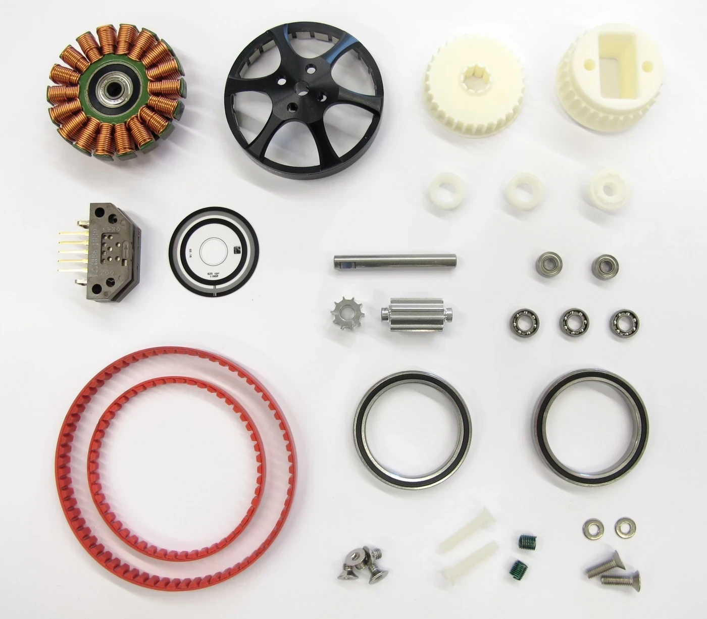
Output torque must overcome seal drag, bearing friction, gear or belt losses, preload and lubricant effects before it accelerates the motor. Some transmissions are geometrically difficult or impossible to backdrive in certain conditions, while others are efficient in both directions.
Efficiency is not one constant. Measure both directions, multiple loads and temperatures. A joint may move easily once rolling but require substantial breakaway torque after a dwell. Contact control cares about the full curve.
| Quantity | What it captures | How to measure | Why it matters |
|---|---|---|---|
| Breakaway torque | Static friction and detent | Slow output torque ramp | Initial contact feel |
| Running resistance | Friction versus speed | Constant-speed backdrive | Sustained manual motion |
| Reflected inertia | Acceleration resistance | Torque and acceleration test | Impact and dynamic response |
| Hysteresis | Direction-dependent loss | Bidirectional torque-speed loop | Control accuracy |
| Electrical damping | Back-EMF and drive state | Repeat open, short and controlled | Power-off behavior |
Reflected motor inertia grows with ratio squared
In an ideal reducer, motor inertia reflected to the output scales approximately with the square of reduction ratio. A higher ratio therefore makes the motor’s rotating inertia more apparent during externally imposed acceleration, even before friction is included.
Low ratio helps transparency but demands a motor capable of higher torque at lower speed. Optimize rotor inertia, motor torque density and transmission together. A large low-ratio motor can still have significant cogging or rotor inertia.
Quasi-direct drive uses a large motor and low reduction
A quasi-direct-drive design pairs a high-torque motor with a low-ratio transmission. The QDD hip-exoskeleton study reports its design using nominal torque, backdrive torque, bandwidth and tracking error, illustrating that transparency must be measured rather than inferred from ratio alone.
Low ratio can improve force control and impact response, but it raises motor size, current and thermal demands. Bearings, belt tension, seals and cabling can dominate small output torque. Package and continuous duty remain system constraints.
Passive backdrivability differs from active compliance
Passive backdrivability is observed without a controller intentionally canceling resistance. Active compliance uses current, torque sensing or model compensation to create a commanded response. Active control can reduce apparent friction but depends on sensors, power, delay and stable gains.
Report both states. Test drive-disabled, zero-current and controlled conditions separately. During a fault, the user may experience passive friction, a braking state or a holding brake rather than the nominal active impedance.
Motor electrical state changes the resisting torque
An open-circuit permanent-magnet motor produces voltage with speed but little current, so electromagnetic damping is limited. Shorted phases or a drive that clamps the bus allow current and can create strong braking torque. Active current control can add or cancel torque within limits.
Define bus voltage, drive mode, phase configuration and overvoltage behavior. External motion can regenerate energy into the DC bus. Protection may deliberately increase resistance or disable motion, changing the backdrive test.
| Electrical state | Expected effect | Test control | Safety concern |
|---|---|---|---|
| Phases open | Low current damping | Confirm true isolation | Bus and connector voltage |
| Phases shorted | Speed-dependent braking | Known short path | Heating |
| Drive enabled, zero command | Controller-dependent torque | Log current and mode | Bias or instability |
| Friction compensation | Lower apparent resistance | Known model and limits | Unexpected motion |
| Holding brake engaged | Mechanical restraint | Brake state verified | Not a backdrive condition |
Backdrivability tests need controlled speed and direction
Use a torque transducer or calibrated force and lever arm at the output. Drive the joint slowly through both directions to measure breakaway and running resistance, then apply acceleration profiles to identify inertia. Repeat across position because gear and cable effects can vary.
Measure temperature, dwell time and lubrication state. Report torque-speed loops rather than one hand-feel adjective. A robot joint intended for physical interaction should also be tested under representative contact impacts and controller latency.
Output sensing reveals resistance hidden by motor encoders
A motor encoder measures motion upstream of the transmission. Backlash, belt stretch and structural compliance can separate motor and output behavior. An output encoder or external reference reveals actual joint motion and helps distinguish friction from elastic windup.
Synchronize motor angle, output angle, torque and current. Direction reversals show lost motion and hysteresis. Do not tune compensation from motor-side data alone when contact occurs at the output.
Easy backdrive is not correct for every axis
Gravity-loaded axes may need a brake or counterbalance. High-load industrial joints may prioritize stiffness and holding over manual motion. Backdrivability can allow environmental disturbances to move the robot unless active control resists them.
Set the required passive resistance and active impedance for each axis and operating state. Consider maintenance, transport, power loss and emergency stop. The safest state may intentionally be less backdrivable than the normal contact-control state.
Design transparency through mechanics, sensing and control
Reduce unnecessary ratio, preload, seal drag and cable friction. Select motor inertia and cogging carefully. Then add current calibration, output sensing and stable compensation where the task needs more transparency.
Validate the complete joint over torque, speed, position, temperature and life. Choose the architecture whose passive and active behavior both fit the robot state machine, not the one that is easiest to move in a single bench demonstration.
- Measure at the joint output in both directions.
- Fix motor-phase and drive state for every test.
- Separate breakaway friction, running drag and inertia.
- Compare passive and actively compensated behavior.
- Include power loss, brake and regeneration states.
Frequently asked questions
Does backdrivable mean easy to move with power off?
Often that is one useful test, but the result depends on motor-phase, drive and brake state as well as mechanics.
Does low reduction always guarantee good backdrivability?
No. Motor inertia, cogging, belt tension, seals, bearings and electrical damping can still dominate.
Can a torque sensor make a high-ratio joint backdrivable?
It can support active compliance, but it does not remove passive inertia, friction or fault-state behavior.
Are backdrivability and compliance the same?
No. Backdrivability concerns reverse motion under external torque; compliance concerns deformation under load.
What test should come first?
Measure output breakaway and running torque versus speed in defined electrical states before adding active compensation.
Mechanical Transparency Note
Backdrivability is a measured system property that depends on speed, direction, temperature, position and electrical state. Separate passive mechanics from active control and verify normal, fault, power-loss and brake behavior at the output.