Backlash, lost motion, hysteresis and torsional stiffness describe different parts of a robot reducer’s bidirectional torque-angle behavior. Backlash is mechanical free play near load reversal. Lost motion is commonly a low-torque reversal measurement that can include play, friction and elastic effects. Hysteresis is path-dependent angle difference, while torsional stiffness is the local slope of torque versus angular deflection.
Those terms are sometimes used differently by suppliers, so a bare arcminute or newton-meter-per-radian value is not enough. The input constraint, output bearing support, applied torque, measurement location, temperature, speed, lubrication and assembly all affect the result. A complete robot joint can behave differently from a reducer tested alone.
Read this with the robot reducer comparison and strain-wave reducer guide. Use the current supplier definition and test method before putting catalog values into a joint error budget.
Backlash is free play, not every reversal error
Pure mechanical backlash is the angular interval in which an input direction change does not yet move the output because mating surfaces have not re-engaged. It is most visible near zero load. Bearings, seals, preload and measurement resolution can make that interval difficult to isolate in a finished reducer.
A zero-backlash label does not mean zero joint error. Gear teeth, shafts, bearings, flexsplines, housings and fasteners deflect under torque. Friction can hold an output until breakaway, and encoder location can hide transmission error. Backlash should therefore be one line in the error budget rather than a synonym for total accuracy.

Lost motion is a low-torque reversal measurement
Harmonic Drive’s technical materials distinguish lost motion from true backlash and define values under stated low-torque conditions. Other manufacturers may use a different torque window or calculation. Always copy the supplier’s exact definition into a comparison sheet.
A typical test approaches the same small positive and negative torque from opposite directions and measures the angular separation. That width can contain tooth clearance, frictional sticking and elastic recovery. It is useful for small command reversals, but it does not describe deflection at rated torque or dynamic tracking by itself.
| Term | What it describes | Typical evidence | Common mistake |
|---|---|---|---|
| Backlash | Mechanical free angular play | Near-zero-load reversal | Calling all hysteresis backlash |
| Lost motion | Low-torque reversal width | Specified positive and negative torque | Ignoring the torque definition |
| Hysteresis | Path-dependent loop separation | Bidirectional torque-angle curve | Reporting one point only |
| Torsional stiffness | Local torque-angle slope | Defined load region | Assuming the curve is linear |
| Joint accuracy | End-to-end task error | Installed robot measurement | Equating it with reducer accuracy |
Hysteresis captures direction-dependent behavior
Load the output in one direction, unload it, reverse the torque and return. If the angle at a given torque depends on the path, the curve forms a loop. Friction, preload, contact migration and material elasticity contribute. The loop area also reflects energy dissipated during the cycle.
Report the torque range, ramp rate and cycle history with the loop. Static and moving tests need not match because lubrication and friction change with velocity. A controller that repeatedly reverses a joint near contact can experience the central part of the loop more often than the full rated-torque envelope.
Torsional stiffness can have several regions
Torsional stiffness is the change in torque divided by angular deflection over a defined portion of the curve. The inverse quantity is compliance. Many reducer curves are nonlinear because contact area, bearing loading and elastic elements change as torque increases. One fitted slope can conceal a softer low-load region or a stiffer high-load region.
Use the manufacturer’s specified regions when available, and retain the original torque-angle data. Convert units carefully: Nm/rad, Nm/degree and Nm/arcmin differ by fixed factors. When reducers are placed in series with shafts, bearings and a flexible housing, compliances add and the weakest element can dominate.
| Test input | Record | Why it matters | Control implication |
|---|---|---|---|
| Small reversal | Angular dead zone | Play and sticking | Limit-cycle risk |
| Slow torque ramp | Full loading loop | Hysteresis and regional slope | Feedforward model |
| Several speeds | Dynamic loop shift | Lubrication and damping | Tracking bandwidth |
| Cold and hot states | Thermal shift | Preload and viscosity | Warm-up compensation |
| Before and after life test | Permanent change | Wear and settling | Maintenance threshold |
Reducer architecture changes the dominant error
A strain-wave reducer intentionally deforms a flexspline and can achieve very small geometric backlash, yet the compliant component creates load-dependent twist. A precision cycloidal reducer uses multiple contacts and preload for stiffness and shock capacity, but bearings, pins and assembly still influence reversal behavior.
Planetary stages can accumulate tooth clearance across stages and show carrier or shaft deflection. Direct drive removes gear-mesh backlash but retains motor, bearing and structure compliance. Nabtesco product information illustrates why RV-family precision and stiffness claims must be read with product size and load conditions.
Build the joint error budget from the load path
Start with the output torque and moment created by payload, link weight, acceleration and contact. Allocate allowable end-effector error among encoder offset, transmission reversal, elastic deflection, bearing motion, housing distortion, link bending and thermal change. Joint-angle error maps to task error through the robot pose and Jacobian.
Include every series element between the measured input and the tool. A stiff catalog reducer mounted in a thin housing can produce a soft joint. An input-side encoder does not directly observe reducer twist, while an output encoder can measure it but adds packaging, calibration and control considerations.
Run a bidirectional torque-angle test on the installed joint
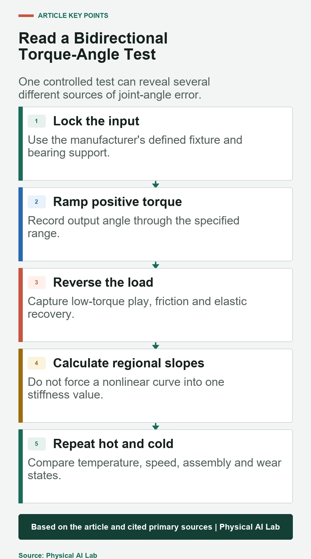
Lock or control the input according to the intended definition. Apply output torque through a calibrated fixture, record output angle and torque, and ramp slowly in both directions. Measure several cycles after mechanical settling. Keep the sensor and fixture resolution well below the smallest claimed angular difference.
Repeat at representative temperatures, speeds, cable states and orientations. Measure the reducer alone when possible, then the assembled joint. The difference reveals bearing, housing and fastener compliance. Store raw traces so a later team can recalculate lost motion or stiffness using a different but explicit definition.
Preload trades clearance for friction and heat
Preload can reduce free play and improve reversal repeatability, but higher contact force raises friction, heat and wear. It can also reduce backdrivability and alter motor-current-to-output-torque calibration. Excessive preload is not a free accuracy improvement.
Assess no-load current, breakaway torque, efficiency, case temperature and life together with the torque-angle curve. Lubricant viscosity and thermal expansion change preload during operation. Verify both cold startup and thermal steady state rather than tuning only after a laboratory warm-up.
Compensation works only inside a validated envelope
A repeatable torque-angle map can support feedforward compensation or dual-encoder control. The estimate needs load, direction, temperature and sometimes speed. Frictional switching and impacts are harder to model than smooth elastic deflection, so compensation should not replace suitable mechanics and feedback.
Validate the corrected joint on trajectories that were not used to fit the model. Inspect reversals, slow contact, fast motion and payload changes. Bound compensation near uncertain regions and monitor residual error. A model from a new reducer may become wrong after settling, lubrication change or damage.
Compare reducers by matched definitions and evidence
A useful comparison table includes ratio, rated and momentary torque, input lock, bearing support, lost-motion torque, stiffness region, temperature, speed, lubrication and life state. The Open Dynamic Robot Initiative shows why motor, transmission, bearings, encoders and housing must be treated as one joint.
Do not rank reducers with one smallest arcminute value. Choose the evidence that matches the task: low-load reversal for pointing, loaded stiffness for machining, impact behavior for legged robots, and thermal drift for long duty. Confirm the final selection with an installed-joint test.
- Record the supplier's exact term and test definition.
- Keep the full bidirectional torque-angle trace.
- Calculate regional rather than assumed constant stiffness.
- Test reducer and assembled joint separately.
- Repeat across temperature, speed and life state.
Frequently asked questions
Does zero backlash mean zero positioning error?
No. Elastic twist, frictional hysteresis, bearings, housing, encoders and calibration still create load- and direction-dependent error.
Are lost motion and backlash the same value?
Not necessarily. Lost motion is often measured over a specified small bidirectional torque range and may include elasticity and friction as well as free play.
Is higher torsional stiffness always better?
It usually reduces loaded deflection, but can add mass, cost and impact transmission. The required stiffness comes from the task error and contact envelope.
Can preload remove backlash?
It can reduce clearance, but usually increases friction, heat and wear and may change backdrivability and efficiency.
When is an output encoder useful?
It is valuable when the controller must observe twist and reversal error after the transmission, provided its resolution, mounting and safety role are validated.
Reducer Accuracy Boundary Note
Reducer terminology and test torque ranges are not universal. Use current supplier data, matched fixtures and a complete installed-joint test before converting a catalog value into robot accuracy or control limits.