Inverse kinematics asks which joint configuration can place a robot frame at a desired position and orientation. Inverse dynamics asks which generalized forces or joint torques would create a desired joint motion, given the robot model, current state and external forces. They solve different layers of the same motion problem.
A target pose alone does not determine actuator torque. The robot needs a chosen joint solution, time parameterization, velocity, acceleration, payload, gravity direction and contact assumptions. Likewise, a torque computation does not choose a collision-free pose. Planning, kinematics, dynamics and feedback must be connected explicitly.
Use this guide with the robot calibration workflow and joint control modes. A numerical solution is usable only after joint, collision, torque, speed and task constraints are checked.
Forward kinematics defines the geometric model
Forward kinematics maps joint coordinates to the pose of an end-effector or another robot frame. The calculation composes link transformations from a base through the kinematic chain. It uses geometry and joint position, not mass, inertia or applied force.
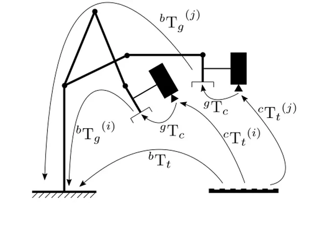
Frame definitions must be correct before solving the inverse problem. OpenCV calib3d documents related rigid transformations used in camera and hand-eye calibration. A solver cannot compensate for a wrong base, tool or camera transform; it will consistently reach the wrong physical pose.
Inverse kinematics maps a task pose to joint candidates
Given a desired end-effector pose, IK finds joint coordinates that satisfy the geometric relationship within tolerance. A six-axis arm can have several valid branches, a redundant arm can have infinitely many solutions, and some targets have none because they lie outside the workspace or violate constraints.
Analytic solvers provide closed-form branches for supported geometries. Numerical solvers iteratively reduce pose error from an initial seed and are more general, but can converge to different solutions or fail near difficult configurations. Report residual error, iterations, seed and termination condition rather than returning only one vector.
| Question | Inverse kinematics | Inverse dynamics | Additional check |
|---|---|---|---|
| Primary input | Desired pose and geometry | q, qdot, qddot and model | Frames and units |
| Primary output | Joint configuration | Joint forces or torques | Actuator mapping |
| Includes mass? | No | Yes | Payload identification |
| Includes timing? | Not by pose alone | Needs motion derivatives | Trajectory generation |
| Main feasibility | Reach and joint limits | Torque and dynamic limits | Collision and contact |
Multiple IK solutions require a selection rule
A solver should not choose among elbow-up, elbow-down or redundant postures arbitrarily. Selection criteria can include distance from the current state, joint-limit margin, collision clearance, manipulability, visibility, cable routing, torque margin and continuity with the previous solution.
Use the previous joint state as a seed for smooth tracking, but do not let seed continuity trap the arm near a limit or collision. A global planner or explicit posture task can guide branch choice. At discontinuities, replan rather than jumping to a distant valid solution.
Singularities change velocity and force mapping
The Jacobian maps joint velocity to task-space velocity and joint torque to task-space wrench relationships. Modern Robotics presents these kinematic and dynamic foundations. Near a singularity, some task directions require very large joint speeds or lose independent motion authority.
A damped pseudoinverse can bound numerical amplification, but it trades task accuracy for stability. Monitor singular values, condition metrics and commanded joint rate. Task scaling, posture adjustment or replanning may be safer than increasing damping after the robot has already entered a poor configuration.
A trajectory adds velocity and acceleration to pose
A path specifies a geometric sequence, while a trajectory assigns time. Joint positions q(t) produce joint velocity and acceleration references that inverse dynamics needs. Time scaling can turn the same path from a gentle motion into one that exceeds motor speed, torque or bus-power limits.
Ensure position, velocity and acceleration are sufficiently continuous for the controller and mechanism. Discontinuous acceleration can demand impulsive torque. Check the interpolated trajectory rather than only waypoints, because joint limits, collision and singularity can be violated between sampled poses.
Inverse dynamics maps desired motion to generalized effort
For a rigid robot, inverse dynamics commonly evaluates inertia, velocity-dependent terms, gravity and external forces to estimate generalized forces. The Underactuated Robotics notes provide model-based control context across fully actuated, floating-base and contact systems.
The usual inputs are q, qdot, qddot, model parameters and known external wrench. The output may be joint torque for fixed-base revolute joints or a larger generalized-force vector for floating systems. Motors may then require conversion through transmission ratio, efficiency and torque constants.
| Model term | Physical source | Required evidence | Common error |
|---|---|---|---|
| Inertia | Mass distribution | Link and payload parameters | Using nominal payload |
| Gravity | Mass and orientation | Base gravity frame | Wrong sign or frame |
| Velocity terms | Coriolis and centrifugal effects | Joint velocity | Noisy differentiation |
| Friction | Bearings and transmission | Bidirectional identification | One constant efficiency |
| External force | Contact and tool load | Wrench and contact model | Assuming free space |
Contact changes the dynamics problem
When a foot, wheel or tool contacts the environment, contact forces and constraints enter the equations. A fixed-base arm touching a surface can become a closed-chain system. A legged robot must satisfy friction, unilateral contact and balance conditions while distributing effort across multiple contacts.
Unknown contact cannot be repaired by an IK pose alone. Estimate or plan the contact mode, define allowable motion and force directions, and include external wrench evidence. Verify that the intended solution does not require pulling through a unilateral contact or exceeding a friction cone.
Model error makes feedback essential
Inverse dynamics is feedforward based on an estimated model. Payload changes, cable forces, friction, temperature and flex invalidate parts of that estimate. Position, velocity, torque or task-space feedback corrects residual error and rejects disturbances within the available bandwidth.
Do not increase model-based torque until signs, units and frames are verified. Start with gravity compensation and slow motion, compare measured current or torque, then expand the envelope. Apply independent position, speed, current, torque and workspace limits throughout commissioning.
Software interfaces may hide the solved layer
A package can expose IK without dynamic feasibility or provide inverse dynamics without collision checking. Orocos KDL documentation covers kinematic and dynamic solvers, but the surrounding application must still supply calibrated models, constraints and controller integration.
Inspect units, joint ordering, base convention, gravity vector and tool frame. Record model and configuration versions with results. A solver returning success means its numerical termination conditions were met; it does not certify that the physical robot can execute the command safely.
Validate the chain from task request to measured effort
Test reachable and unreachable poses, multiple branches, joint-limit edges and singular regions. Then time-parameterize selected paths and compare predicted torque with actuator evidence across payload, direction, speed and temperature. Include collision and contact cases that the real task will encounter.
Log desired and measured task pose, q, qdot, qddot, torque command, current, saturation and solver status on one clock. This lets the team separate geometric error, trajectory error, model error and control error instead of blaming every failed reach on IK.
- Calibrate base, tool and joint references first.
- Retain all relevant IK candidates and selection costs.
- Check singularity, collision and limits along the full path.
- Provide timed derivatives and external-force assumptions to dynamics.
- Compare model torque with measured actuator evidence.
Frequently asked questions
Does inverse kinematics calculate motor torque?
No. It calculates joint configurations for a task pose. Torque requires motion timing, a dynamic model, payload and external-force assumptions.
Why can IK return several answers?
Different joint branches or redundant postures can produce the same end-effector pose. A task-specific selection criterion is required.
Can inverse dynamics replace feedback?
No. It is model-based feedforward; feedback is needed to correct parameter error, friction, disturbances and execution mismatch.
What happens near a singularity?
Some task directions lose authority or demand very large joint motion. Damping can help numerically, but posture change or replanning may be required.
Which calculation comes first?
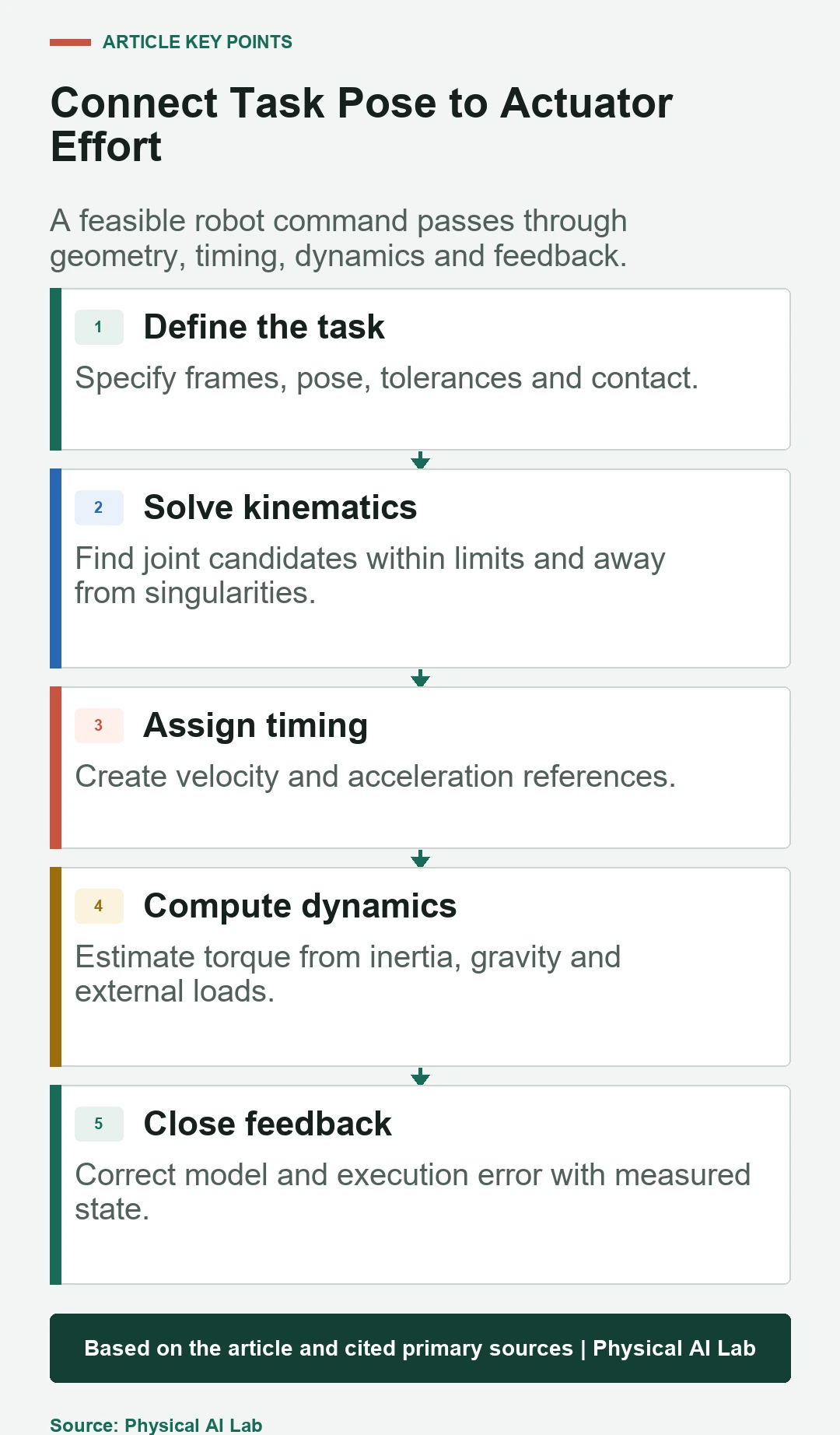
Usually a task pose is converted to a selected joint path, timing adds derivatives, and inverse dynamics estimates effort before feedback executes the motion.
Robot Model Boundary Note
IK success does not prove collision, dynamic or hardware feasibility, and inverse-dynamics output is only as accurate as the model, state and contact assumptions. Validate the complete command chain on the robot with independent limits.