Robot calibration identifies parameters or coordinate transforms that make measured robot geometry agree with the physical system. Joint-zero, kinematic, tool-center-point, camera-intrinsic and hand-eye calibration solve different errors. Running the wrong procedure can produce a precise estimate of the wrong quantity.
Start by asking where the task error appears and which frame or parameter could cause it. Repeatability describes returning to the same pose; absolute accuracy describes agreement with an external reference. A repeatable robot can still have a consistent position error that calibration improves.
Use this guide with the encoder guide and virtual commissioning guide. Calibration does not remove structural deflection, backlash, sensor noise or thermal drift; verify the final task under representative load and temperature.
Identify the wrong transform or parameter first
Draw the chain from world and robot base through joints, flange, tool, camera and target. Compare observed error across robot poses, camera viewpoints, tools and payloads. A constant tool offset suggests a different cause than pose-dependent kinematic error.
Separate measurement error from robot error. External trackers, calibration targets and fixtures have their own uncertainty. Define the accuracy requirement and uncertainty budget before collecting more decimal places than the reference supports.
Joint-zero calibration restores encoder references
Joint-zero calibration estimates the offset between the encoder reference and the mechanism’s defined joint angle. It may use index marks, hard stops, precision fixtures, secondary sensors or mastering tools. An offset propagates through forward kinematics and becomes pose-dependent tool error.
Reference every affected joint using a documented direction and load condition. Backlash and gravity can change the apparent zero depending on approach. Record encoder counts, offsets, temperature and mechanical state so the result can be reproduced after service.
| Calibration type | Estimated quantity | Required observations | Typical symptom |
|---|---|---|---|
| Joint zero | Encoder-to-joint offset | Reference pose or fixture | Pose-dependent tool error |
| Kinematic | Link lengths and axis geometry | Many measured robot poses | Systematic workspace error |
| TCP | Tool transform at flange | Multiple orientations or contacts | Tool-tip offset |
| Camera intrinsic | Focal and distortion parameters | Target images across frame | Image reprojection error |
| Hand-eye | Camera-to-gripper or base transform | Robot poses and target observations | Vision-guided placement offset |
TCP calibration locates the tool relative to the flange
Tool-center-point calibration estimates the position and often orientation of the working point in the flange frame. Common methods move several tool orientations around one fixed physical point or align tool axes to a reference.
Use diverse orientations while keeping the reference point stable. A loose tool, flexible extension or inaccurate contact fixture corrupts the estimate. Validate by approaching independent points and orientations not used in the fit.
Camera intrinsics must be calibrated before geometry fusion
Camera intrinsics include focal lengths, principal point and lens distortion. Hand-eye calibration assumes image observations have already been converted through a suitable camera model. Poor intrinsics can appear as a robot-camera transform error.
OpenCV’s calibration documentation provides camera and hand-eye functions with explicit coordinate-transform conventions. Capture a calibrated target across the image area, depth and orientation, and inspect reprojection residual patterns rather than one average number.
Hand-eye calibration connects camera and robot frames
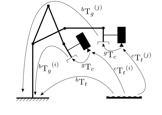
Eye-in-hand calibration estimates the fixed transform between a camera and moving gripper. Eye-to-hand calibration estimates the relationship between a fixed camera and robot base or working frame. The input transforms and desired output differ, so label every superscript and direction.
For eye-in-hand, multiple robot motions and target observations form an AX=XB relationship. The solution depends on accurate robot poses and target detection. Use many well-separated rotations and translations, not a cluster of nearly identical views.
AX equals XB needs observable, diverse motion
OpenCV notes that at least two motions with non-parallel rotation axes are needed to determine the hand-eye transform and recommends using many more poses. Degenerate motion leaves some parameters weakly observed even if the solver returns a result.
Plan poses that span orientation axes, distance and workspace while keeping the target visible and sharp. Reject frames with motion blur or ambiguous target detection. Compare multiple algorithms and inspect transform consistency, but select using independent task error.
| Data-quality check | Good evidence | Failure pattern | Corrective action |
|---|---|---|---|
| Rotation diversity | Several nonparallel axes | Unstable orientation | Add distinct wrist rotations |
| Translation diversity | Broad useful baseline | Depth sensitivity | Change distance and position |
| Target coverage | Image area and angle variety | Edge distortion residuals | Improve intrinsic dataset |
| Robot pose quality | Settled, timestamped states | Inconsistent transform | Synchronize and hold |
| Validation split | Unseen poses and targets | Training-only accuracy | Reserve independent trials |
Kinematic calibration estimates structural geometry
Kinematic calibration adjusts link lengths, joint-axis directions, base frame and related parameters using external pose measurements. Parameter identifiability matters because several errors can produce similar tool displacement over a limited dataset.
Use a parameter model appropriate to the robot and avoid fitting unobservable combinations. Regularize or constrain known geometry. Validate across the workspace and payload conditions; do not interpret a lower fitting residual as guaranteed task accuracy.
Calibration and validation data must be separated
A solver will look best on the observations it used. Reserve poses, target placements and task trajectories for validation. Report position and orientation error distributions, worst cases and spatial pattern rather than only a root-mean-square value.
Compare before and after results using the same independent reference. Investigate outliers for collision, backlash, target movement, image ambiguity or timestamp error. A few large errors can matter more to production than the mean.
Temperature, load and collision can change calibration
Robot links, reducers, cameras and mounts expand with temperature. Payload bends the structure. A collision or maintenance event can shift a tool, base or sensor. Calibration is therefore a controlled state with triggers for checking and renewal.
Track warm-up, ambient temperature, payload, tool serial number and fixture state. Use quick verification artifacts between full calibrations. Set thresholds for continuing, recalibrating or inspecting hardware.
Calibrate from stable references toward tools and sensors
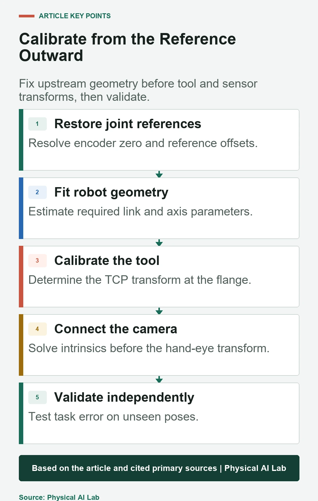
Restore joint references and base geometry before fitting downstream transforms. Calibrate the camera intrinsics before hand-eye. Calibrate the TCP for the installed tool, then validate the combined chain on the real task.
Version parameters, raw observations, software, target geometry and results together. A deployment should know which calibration set is active. Re-run independent accuracy checks after any upstream change.
- Draw and label every coordinate transform.
- Fix joint references before downstream calibration.
- Use diverse, observable poses and accurate targets.
- Reserve independent data for validation.
- Define recheck triggers for load, temperature and service.
Frequently asked questions
Are TCP and hand-eye calibration the same?
No. TCP calibration finds the tool relative to the flange; hand-eye calibration connects a camera to the gripper or robot base.
Can hand-eye calibration use one image?
No. It relies on multiple robot poses and target observations with sufficiently diverse motion.
Does good repeatability eliminate the need for calibration?
No. A robot can repeat a pose precisely while remaining consistently offset from an external coordinate system.
Will joint-zero calibration correct structural bending?
No. It corrects reference offsets; load-dependent deflection and geometry errors require other models or compensation.
When should calibration be repeated?
Recheck after collisions, tool or camera changes, encoder or mechanical service, abnormal error, and significant load or temperature changes.
Calibration Scope Note
Calibration quality is limited by observability, reference uncertainty, synchronization and mechanical stability. Keep fitting and validation data separate, preserve transform conventions, and verify the combined system on independent task-space measurements.