Robot joint gains convert measured error into current, torque, velocity or position correction. Higher proportional gain can reduce error and increase apparent stiffness, but also amplifies delay, noise and flexible resonance. Integral action removes persistent bias but can wind up at limits, while derivative or velocity feedback adds damping and sensitivity to measurement quality.
Most servo joints use cascaded loops. A fast current loop sits inside a velocity loop, which may sit inside a position loop. Each loop sees the closed behavior of the layer beneath it. Tuning an outer loop before the inner loop is stable creates misleading gains and hidden saturation.
Use this guide with the FOC current-control guide and joint actuator test guide. Commission at reduced energy with physical stops, current limits and qualified supervision.
Confirm mechanics and feedback before changing gains
Verify encoder direction, scale, zero, phase order, torque sign and command units. Check bearings, fasteners, transmission play, brake release, cable forces and load fixture. A loose mechanism or wrong sign cannot be repaired with a PID value.
Set conservative current, torque, velocity, acceleration and workspace limits. Establish an emergency stop and safe test position. Use small excitation and record the unpowered or low-gain mechanical response first. Resonance frequency and friction will shape every later result.

The current loop creates motor torque
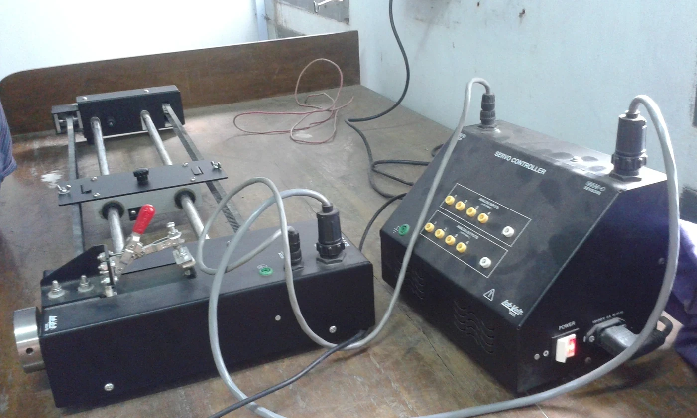
The inner loop regulates phase or torque-producing current at a high and deterministic rate. Its bandwidth is limited by motor electrical dynamics, PWM, current sensing, computation and voltage margin. Poor rotor angle or current sampling can appear as a gain problem.
Tune against measured d-q current or the drive’s documented method. Inspect step response, overshoot, settling, saturation and switching noise. Verify at several rotor angles, bus voltages and temperatures. Do not exceed motor or inverter current and thermal limits for a cleaner plot.
| Loop | Controlled variable | Main limit | Evidence |
|---|---|---|---|
| Current | Motor current | Voltage, PWM and sensing | d-q response |
| Velocity | Joint or motor speed | Inertia and friction | Speed step or sweep |
| Position | Joint angle | Compliance and delay | Tracking and stiffness |
| Task or impedance | Cartesian or force relation | Kinematics and contact | Wrench-motion test |
| Trajectory feedforward | Desired motion terms | Model error and limits | Residual reduction |
The velocity loop adds damping around the plant
With a stable current loop, the velocity controller commands torque or current to reduce speed error. Proportional velocity gain behaves like damping in many joint models. Integral velocity gain can remove steady load error but also accumulate during saturation.
Velocity estimates from encoders contain quantization and noise, especially at low speed. Filtering reduces noise but adds phase lag. Tune the estimator and loop together. Test both directions because friction and gravity make the plant asymmetric.
The position loop sets tracking and apparent stiffness
The outer position loop produces a velocity or torque-related request from position error. Increasing gain can reduce low-frequency tracking error and make the joint feel stiffer, but delay and elastic modes limit the stable bandwidth.
Use trajectories with bounded velocity and acceleration rather than a discontinuous large step on a powerful joint. Measure rise time, overshoot, settling, steady error, following error and peak effort. Inspect current and velocity saturation so a slow response is not incorrectly blamed on low position gain.
P, I and D terms address different behavior
The current control_toolbox PID reference defines proportional, integral and derivative terms plus output limits and anti-windup options. Proportional action follows present error, integral accumulates past error and derivative responds to error rate.
Derivative action can add damping but amplifies measurement noise and is sensitive to sample time. Many cascaded drives use measured velocity instead of differentiating position error directly. Integral action should be added only after proportional behavior and saturation are understood.
Saturation requires explicit anti-windup
Current, torque, speed and voltage commands have limits. If an integrator continues accumulating while the actuator is saturated, the controller can overshoot or recover slowly after the command becomes achievable. Output clamping alone does not remove stored integral state.
Back-calculation and conditional integration are common strategies. Select tracking constants and clamps from the plant and command limits, then test entry and exit from saturation in both directions. Reset or transfer integrator state carefully during mode changes to avoid a command jump.
| Symptom | Possible cause | Evidence | Correction |
|---|---|---|---|
| Fast oscillation | Gain or delay near resonance | Frequency and phase | Reduce bandwidth or notch |
| Overshoot | Low damping or windup | Saturation and integral state | Add damping and anti-windup |
| Slow response | Low gain or active limit | Command versus clamp | Remove bottleneck safely |
| Noisy current | Derivative or velocity noise | Spectrum and raw encoder | Filter or estimator review |
| Load-dependent error | Model or integral shortage | Payload sweep | Feedforward or bounded integral |
Tune from the inside out with bandwidth separation
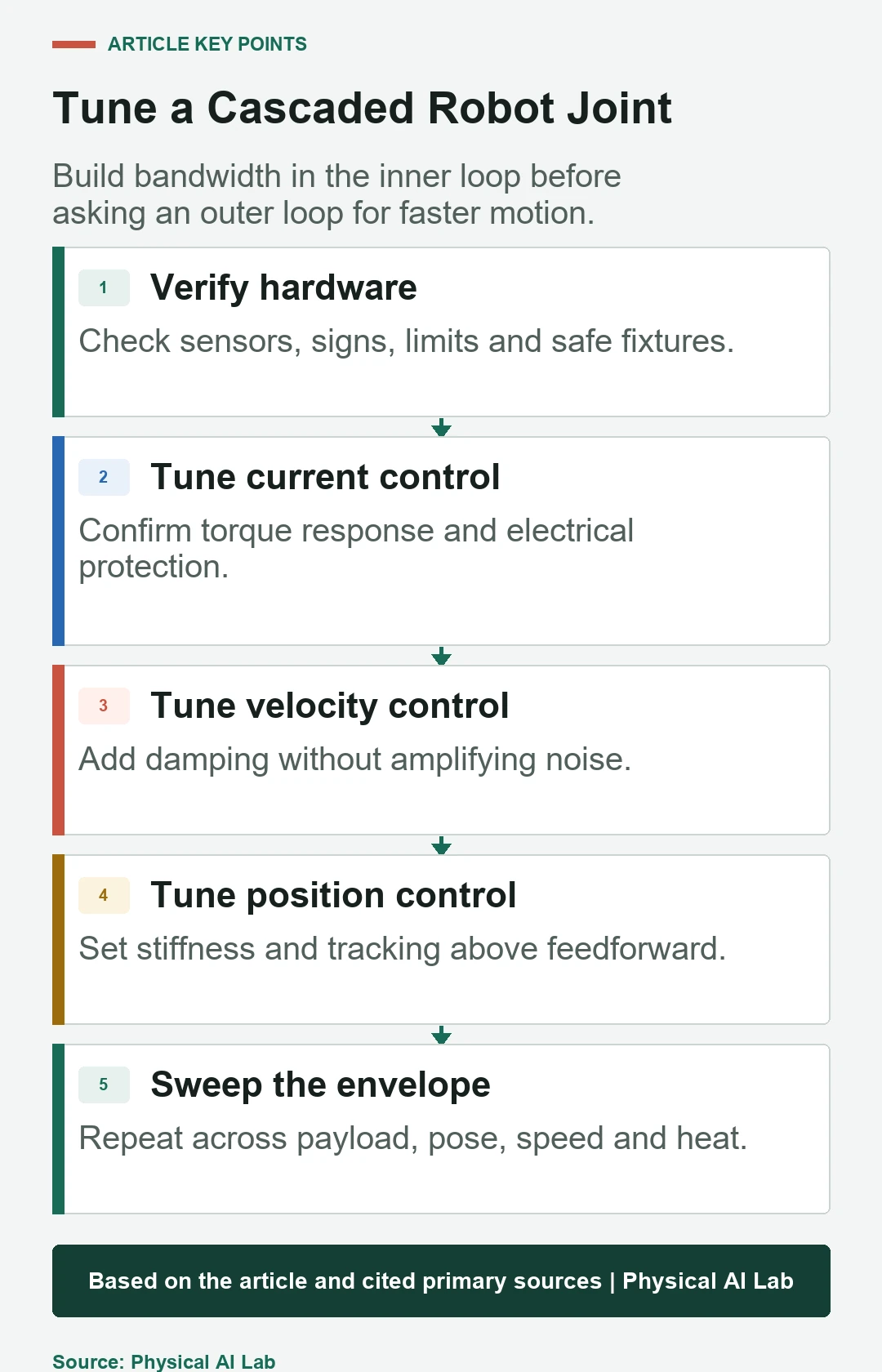
Stabilize and validate the current loop first, then velocity, then position. Keep each outer loop sufficiently slower than the inner closed loop so its command can be realized. Exact ratios depend on delay, mechanics and control design; do not copy a universal bandwidth rule without measurement.
After each stage, test saturation and fault behavior before enabling the next. Save a versioned gain set with sample rate, filters, payload, transmission and firmware. A numeric gain has no portable meaning without those units and conditions.
Frequency response reveals flexible modes
A step response can look acceptable while hiding a narrow resonance excited by other trajectories. Use bounded sine sweep, chirp or frequency-response testing where safe. Compare command and measured position, velocity and torque to identify resonance, antiresonance and phase loss.
Mechanical mode frequency changes with payload, pose, cable and joint temperature. A notch filter can suppress a known mode but adds phase and can become wrong when the mode moves. Validate filter and gains across the full operating envelope.
Feedforward reduces work demanded from feedback
The joint trajectory controller parameters include feedback gains and velocity feedforward for supported interfaces. Model-based gravity, velocity and acceleration feedforward can reduce tracking error without increasing feedback stiffness.
Feedforward needs correct units, timing and plant parameters. It can saturate the actuator or reinforce a sign error. Compare feedback effort before and after addition and retain bounded correction. Update payload and gravity models when tools change.
Validate gains across payload, pose and temperature
Run slow and fast trajectories, reversals, holds, gravity-loaded poses and representative contacts. Repeat with minimum and maximum payload, cold and warm joints, expected bus voltage and communication delay. Monitor error, effort, saturation, noise and temperature.
Define acceptance limits and automatic rollback to a conservative gain set. Fleet or production deployment needs configuration identity and change control. One successful laboratory pose is not evidence of stable full-workspace performance.
- Verify signs, units, sensors and mechanical condition.
- Tune current, then velocity, then position.
- Log commands, limits and integrator state.
- Use frequency evidence for flexible resonances.
- Repeat across pose, payload, speed and temperature.
Frequently asked questions
How high should proportional gain be?
High enough to meet tracking and stiffness needs with measured stability margin across the operating envelope, not simply just below oscillation in one test.
Is integral gain always necessary?
No. Add it when persistent bias must be removed and after saturation and anti-windup behavior are defined.
Will more derivative gain always reduce oscillation?
No. It can add damping but also amplify noise and lose effectiveness through filtering or delay.
Can every joint use the same gains?
Usually not. Inertia, transmission, friction, structure, sensing and load differ by joint and pose.
Can automatic tuning finish commissioning?
It can provide a starting model or gains, but hardware limits, flexible modes, task trajectories, payload and fault behavior still require validation.
Servo Tuning Boundary Note
Gain tuning can create hazardous motion and high current. Use conservative limits and fixtures, follow drive and robot procedures, and validate stability, saturation, thermal behavior and faults across the complete operating envelope.