Robot collision detection identifies external contact by comparing measured or estimated interaction with expected motion and dynamics. Evidence can come from joint torque sensors, motor current, a wrist force-torque sensor, tactile sensing, acceleration or a model-based disturbance observer. Each sees different locations and contains different bias and delay.
Detection is only the first part of risk reduction. The controller must classify or threshold the event, choose a bounded reaction, decelerate or remove torque, coordinate brakes and determine whether recovery is permitted. Detection time, stopping motion and peak contact force need system-level validation.
Use this guide with the robot sensor-fusion guide and joint gain-tuning guide. Collision detection does not replace the applicable risk assessment, protective functions or safety standards.
Direct force sensing observes a designed load path
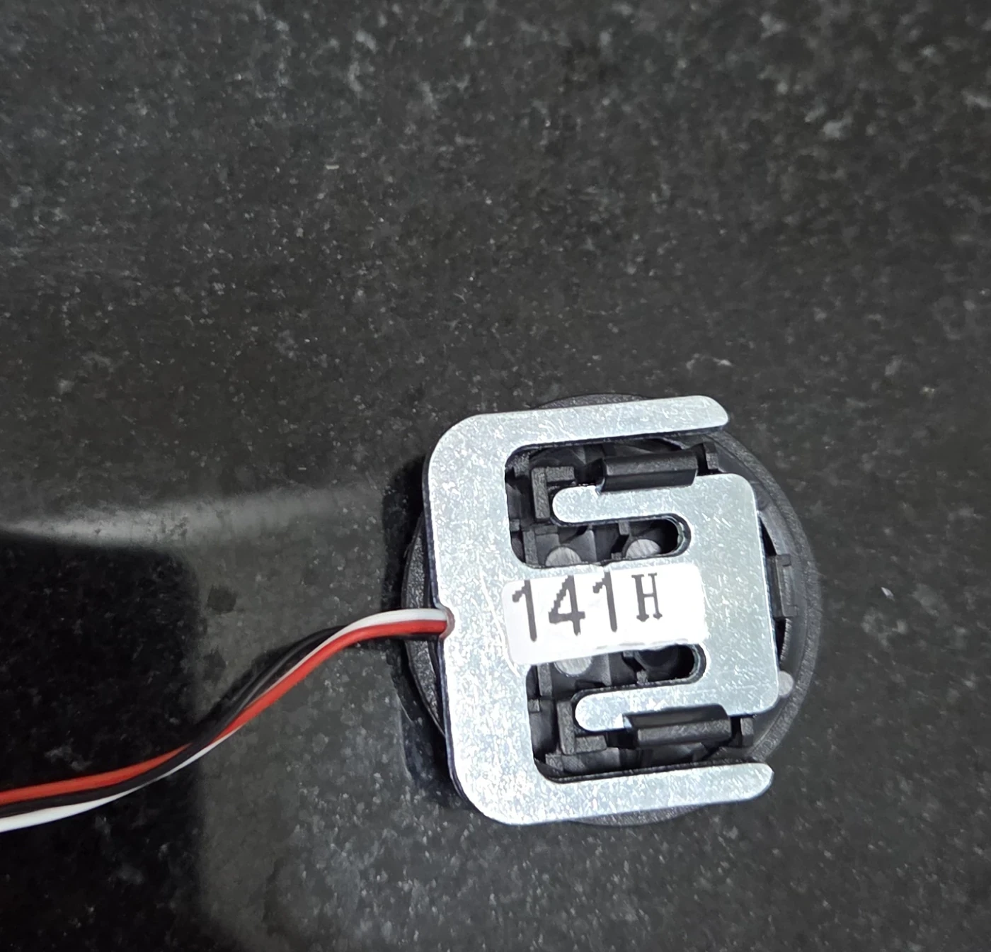
A load cell or force-torque sensor converts structural strain or another physical effect into force evidence. A single-axis load cell is sensitive along its designed axis; a six-axis wrist sensor estimates a wrench at its mounting frame. Neither automatically localizes every collision on the robot.
Sensor placement matters. A wrist sensor observes loads transmitted through the tool but may not see a forearm impact clearly. Joint torque sensors can expose external torque distributed across a chain. Calibrate zero, gain, cross-talk, frame and gravity or tool load for the installed configuration.

Motor current is an indirect torque measurement
A calibrated motor current and torque constant estimate electromagnetic motor torque. Transmission ratio, efficiency, friction, cogging and acceleration separate motor torque from external output torque. Current is widely available but can be ambiguous in high-friction or high-ratio joints.
Use current-sensor timing and the actual drive command path. Bidirectional maps across speed, load and temperature are more useful than one constant efficiency. Keep electrical saturation and current-loop behavior visible, because a clipped current signal can hide the true event magnitude.
| Evidence | Strength | Blind spot | Calibration |
|---|---|---|---|
| Wrist F/T sensor | Direct tool wrench | Body contacts outside path | Tool mass and frame |
| Joint torque sensor | Joint-level external torque | Contact location ambiguity | Zero and cross-talk |
| Motor current | Available in most drives | Friction and transmission error | Torque-current map |
| Disturbance observer | Uses model and state | Model and delay error | Dynamics and friction |
| Tactile skin | Local contact location | Coverage and wear | Surface response |
A disturbance observer subtracts expected dynamics
An observer predicts joint torque from inertia, gravity, velocity, friction and commanded motion, then treats unexplained residual as a disturbance estimate. Momentum-observer approaches can avoid direct acceleration differentiation, but they still depend on model, state and numerical filtering.
Payload error, cable force, brake drag and aggressive acceleration can look like collision. Conversely, filtering can delay a real event. Validate residual distribution for every normal task phase before choosing a threshold. Keep model version and payload identity with the detector configuration.
Thresholds need direction, phase and duration
Franka’s collision behavior API exposes different torque and force thresholds for acceleration and nominal phases. That distinction illustrates why one scalar threshold across all motion is usually inadequate.
Use joint- and direction-specific thresholds where evidence supports them. Combine magnitude with duration, derivative or multi-axis consistency to reject noise without delaying contact excessively. Define separate contact, collision and hardware-limit states rather than one ambiguous alarm.
Low thresholds trade missed events for false stops
Reducing a threshold can detect smaller contact but also trigger on acceleration, friction, model error, cable motion or payload change. Frequent false positives can lead operators to raise thresholds informally or disable detection, creating a worse system.
Quantify true positive, false positive, missed detection and detection delay across labeled trials. Select an operating point from the risk assessment and production cost, not from one demonstration. Monitor distribution shift after maintenance or tool change.
| Test dimension | Examples | Record | Why it matters |
|---|---|---|---|
| Contact location | Tool, link, joint cover | Detection and force | Observability changes |
| Direction | Normal, tangential, axial | Axis residual | Threshold asymmetry |
| Robot state | Hold, acceleration, reversal | False and true events | Expected dynamics differ |
| Impact object | Soft, rigid, edged | Peak and impulse | Sensor bandwidth |
| Environment | Payload, cable, temperature | Baseline shift | Model validity |
Contact location is not always observable
Joint-torque residuals can sometimes support contact localization by comparing candidate Jacobians, but different contact points can produce similar generalized torque. Wrist sensing only observes loads through its chain. Tactile coverage improves local evidence but adds calibration and durability constraints.
Report whether the detector only flags contact or also estimates force, direction and location. Validate each claim separately with reference instrumentation. Do not present a rough link classification as centimeter-accurate localization.
Filtering trades noise for detection delay
Low-pass filters, moving windows and observers reduce high-frequency noise but delay threshold crossing. Different filters also change peak amplitude. Measure total latency from physical contact to decision, including sensor sampling, drive transport, computation and state-machine update.
Use an instrumented impact or force reference with synchronized clocks. Characterize rigid and soft contacts and the robot’s own vibration. A detector tuned on slow pushing may miss a short impact, while one tuned to impulses may false-trigger on gear ripple.
The reaction determines residual contact energy
After detection, options include controlled deceleration, velocity scaling, compliant retreat, torque removal or a safety stop. The correct reaction depends on gravity, payload, contact geometry and safety architecture. Simply disabling torque can let a gravity-loaded arm fall.
Measure detection distance, controller response, braking, mechanical coast and rebound as one stop path. Coordinate holding brakes and energy removal. Define what information is required before automatic recovery and when operator inspection is mandatory.
Collision detection is not automatically a safety function
ISO 10218-1:2025 addresses safety requirements for industrial robots, while integration is covered by the companion system standard. A software residual threshold does not become safety-rated merely because it stops a robot in a laboratory test.
Required performance level or safety integrity, architecture, diagnostics, systematic capability and validation come from applicable risk assessment and standards. Use certified or validated protective functions where required. Keep research collision detection as an additional layer unless its complete safety role is established.
Validate normal work, collisions and detector faults
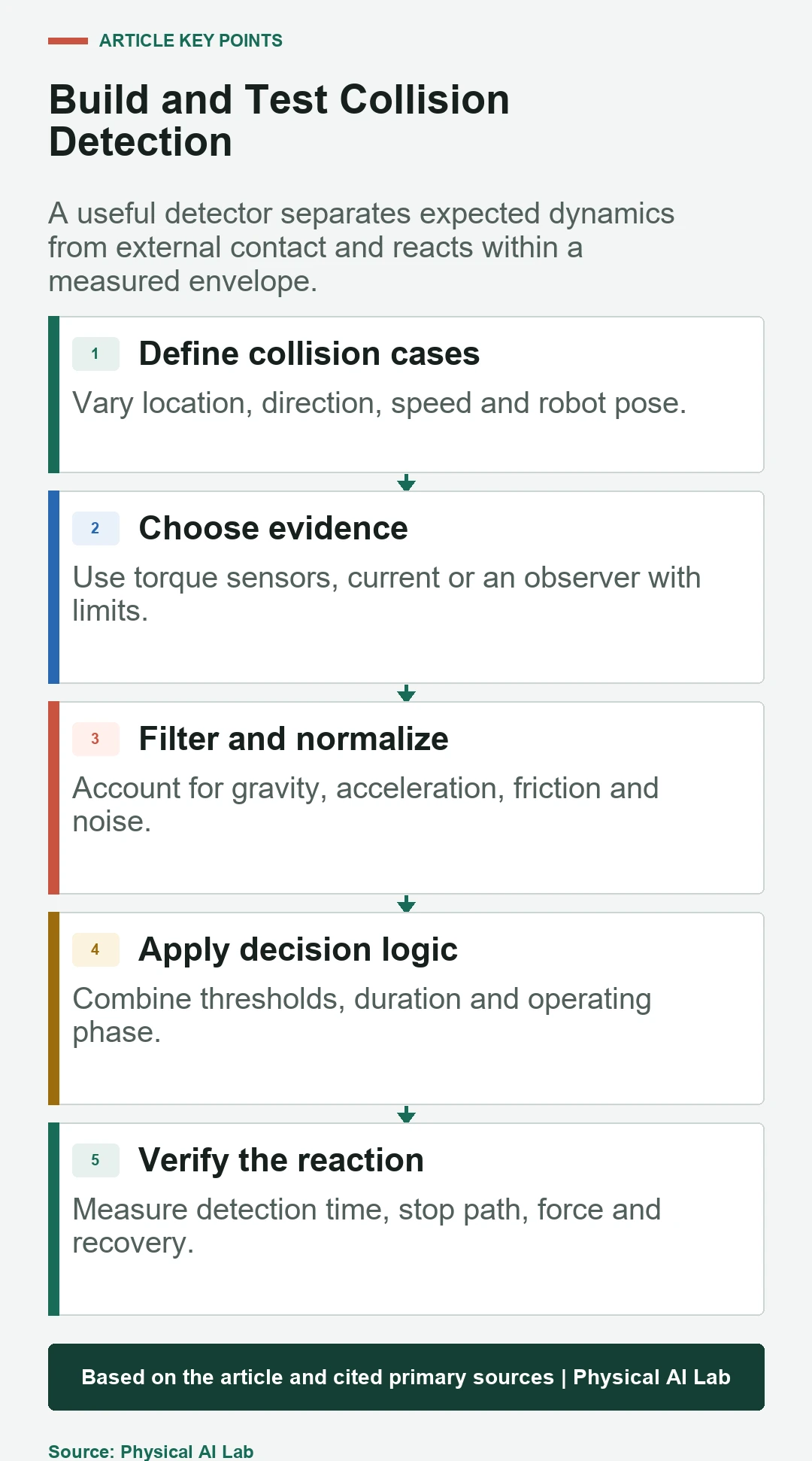
Collect normal trajectories across payload, speed, pose, temperature and wear, then staged contacts across location, direction, speed and object stiffness. Use reference force and synchronized video or instrumentation. Record raw signals, estimates, thresholds, decision and full reaction.
Inject sensor dropout, stale state, model mismatch and saturated commands. Verify detector health monitoring and fallback. Revalidate after gain, filter, firmware, tool or mechanical changes because each can shift residual distributions and stopping behavior.
- Define which contact locations and forces are observable.
- Calibrate sensing and expected dynamics together.
- Set phase-aware thresholds from labeled trials.
- Measure physical contact-to-decision and stop path.
- Keep required protective safety functions independent and validated.
Frequently asked questions
Can motor current alone detect a collision?
It can provide useful evidence, but friction, transmission losses, acceleration and current calibration limit accuracy. Validate it for the specific joint and task.
Are lower thresholds always safer?
No. They reduce detectable force but can create false stops and operational bypass. Select thresholds from measured error distributions and risk requirements.
Can one wrist force sensor detect every body collision?
No. It mainly observes loads transmitted through the tool-side load path and may be insensitive to contacts elsewhere.
Should the robot immediately disable motors after detection?
Not always. Gravity and contact can make uncontrolled torque removal hazardous; the reaction must be designed with braking, holding and system risk.
Which condition is most often missed in validation?
Motion phase and payload are commonly overlooked. Acceleration, reversal, cable force and temperature can shift normal residuals enough to change both false positives and misses.
Collision Detection Boundary Note
Collision detection performance depends on sensing, model, motion, payload, filters and reaction. It is not automatically a safety-rated function; apply the required risk assessment, standards and independently validated protective measures.