Cogging torque is a position-dependent torque produced by the interaction of permanent-magnet rotor fields with stator-slot geometry. It can be present with no commanded current, which is why it is also called detent or no-current torque. At low speed it can create discrete motion, speed variation or a repeating feel at the shaft.
Torque ripple is the broader variation around desired electromagnetic torque. Cogging can contribute, but commutation, current-control error, inverter dead time, bus ripple, magnetic harmonics, friction and load mechanics can also produce ripple. A time trace that looks periodic does not identify the cause by itself.
Use this guide with the field-oriented motor-control guide and robot joint friction-compensation guide. Diagnose the physical source before building a compensation table.
Cogging exists without drive current
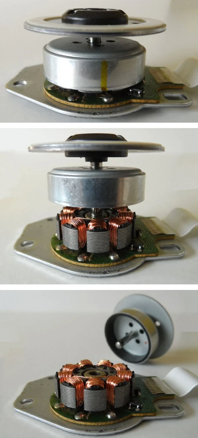
As rotor magnets move past slots and teeth, magnetic reluctance changes with angle. The rotor is attracted toward positions of lower magnetic energy, producing a periodic torque even when the windings are unenergized. Pole and slot combination, magnet shape, skew, slot opening and air gap shape its order and amplitude.
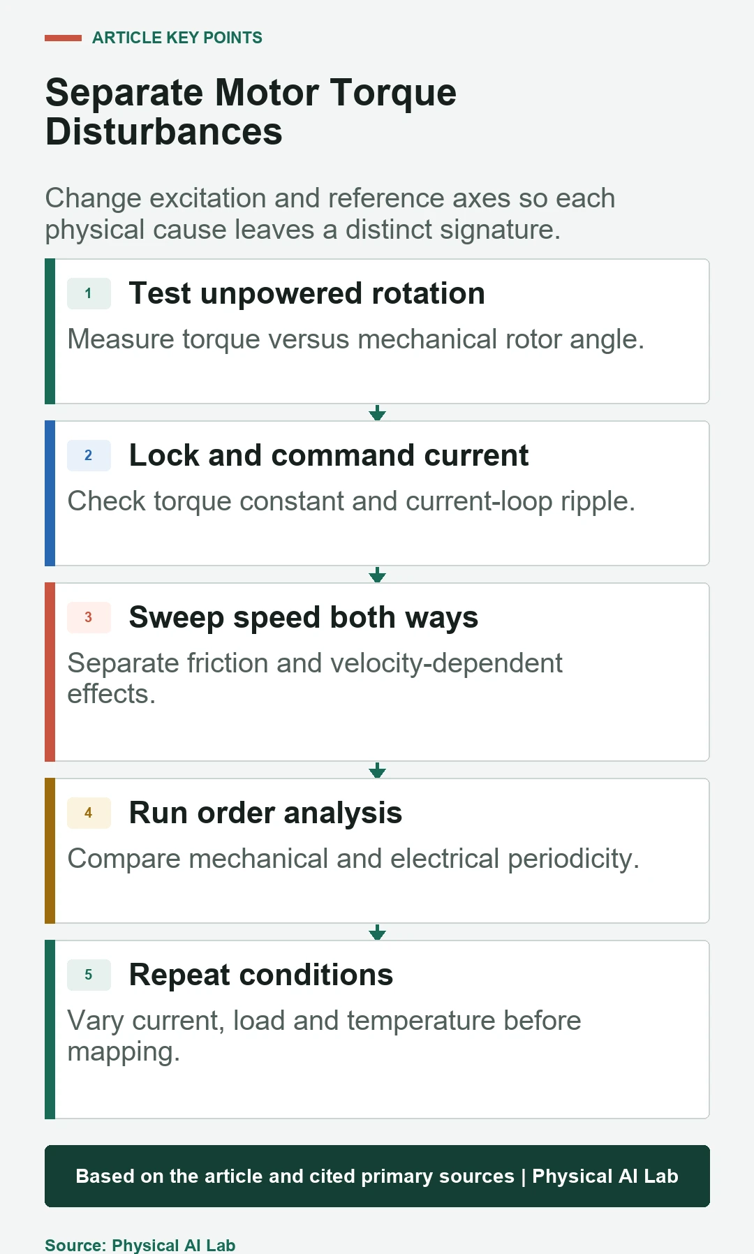
Disconnect or command zero current under a safe test setup and rotate the rotor slowly with a calibrated torque sensor. Bearings, seals and transmission friction remain in the measurement, so test both directions and several speeds. The component that repeats with mechanical angle and survives current removal is consistent with cogging but still needs separation from mechanical detents.

Torque ripple includes several driven effects
Electromagnetic torque depends on current, back-EMF shape, rotor-angle estimation and magnetic parameters. Six-step commutation creates transition-related ripple; sinusoidal FOC can reduce some harmonics but current-sensor error, bandwidth, inverter nonlinearity and spatial harmonics remain. DC-bus ripple can distort current and torque.
The Texas Instruments torque-ripple overview distinguishes commutation and bus-voltage mechanisms, while its cogging article identifies cogging as a no-current, position-dependent source. Those motor examples explain mechanisms, not the final amplitude in a geared robot joint.
| Source | Present at zero current? | Reference variable | Condition sensitivity |
|---|---|---|---|
| Cogging | Yes | Mechanical rotor angle | Magnet and slot geometry |
| Commutation ripple | No | Electrical commutation phase | Speed and current |
| Current-loop ripple | No | PWM and electrical frequency | Bandwidth and sensing |
| Bus ripple | No | Supply phase or bus voltage | Load and capacitance |
| Friction | Often motion dependent | Velocity and direction | Temperature and preload |
Mechanical and electrical angle expose different orders
Plot torque against mechanical rotor angle for repeated revolutions. Cogging should align to angle even when speed changes. Plot driven effects against electrical angle and current phase as well. Electrical order is related to pole pairs, while slot and pole combinations can create higher mechanical orders.
Order tracking normalizes frequency by rotational speed, making angle-synchronous components visible during a speed sweep. A fixed structural resonance appears differently from a component locked to rotor order. Preserve encoder index and electrical zero so phase can be compared across runs.
Start with a no-current rotation test
Use a low-friction fixture, appropriate shaft coupling and torque sensor whose range resolves the expected ripple. Rotate slowly enough to avoid inertial torque but fast enough to reduce stop-start stick-slip. Record angular position, torque, direction, speed and temperature on one time base.
Average many revolutions only after aligning angle. Averaging time samples at varying speed smears the waveform. Compare clockwise and counterclockwise traces: a symmetric angle-locked component suggests cogging, while a direction-dependent offset or loop indicates friction and hysteresis.
Driven tests separate torque constant and current quality
Lock or quasi-statically hold the rotor at several angles and command bounded q-axis current to measure torque versus current. This reveals angle-dependent torque constant, sensor zero and saturation. Then run controlled speed sweeps while logging phase currents, dq current, bus voltage and rotor electrical angle.
Correlate torque ripple with current error rather than only current command. PWM sampling, dead time and rotor-angle offset can produce harmonics. Repeat at several current levels: true cogging remains at zero current, while electromagnetic ripple typically scales or changes with current and voltage.
| Test | Excitation | Primary observation | Separates |
|---|---|---|---|
| Unpowered rotation | External slow drive | Torque versus mechanical angle | Cogging and friction |
| Locked rotor | Commanded current | Torque versus angle and current | Torque constant |
| Constant-speed sweep | Driven rotation | Order spectrum | Electrical and mechanical orders |
| Bus variation | Supply or load change | Torque and voltage | Bus-induced ripple |
| Temperature repeat | Warm and cold | Amplitude and phase | Thermal drift |
FOC reduces some ripple but not geometric cogging
Field-oriented control regulates torque-producing current in a rotating frame and can create smoother electromagnetic torque than six-step commutation. Its result depends on current sensing, rotor-angle accuracy, PWM, loop bandwidth and motor saliency. It does not remove the no-current magnetic attraction created by slots and magnets.
Improve current-loop evidence before attributing every oscillation to cogging. Use the joint gain-tuning guide to check bandwidth and resonance. An aggressive speed loop can amplify a small periodic disturbance or excite the transmission, making the measured joint motion look worse than motor torque alone.
A compensation map needs angle registration
A common servo method learns cogging torque versus rotor angle and commands the opposite feedforward waveform. The map must use the same mechanical reference, interpolation and direction convention at runtime. Encoder replacement, pole alignment or transmission assembly can shift its phase.
Build the map at multiple temperatures and loads when amplitude changes materially. Filter measurement noise without erasing real high-order content. Limit and ramp compensation so a bad index or corrupt table cannot create a large command. Validate both torque reduction and position tracking.
Friction, backlash and resonance can mimic cogging
Static friction produces breakaway, Coulomb friction changes sign with direction, and viscous friction grows with speed. Backlash creates lost motion and impact around reversals. Flexible transmission modes can amplify periodic torque at particular speeds. None is corrected reliably by one rotor-angle table.
Compare the reducer backlash and stiffness guide and repeat tests before and after the transmission where possible. If a spectral peak moves with speed, identify its order; if it stays near one frequency, investigate a structural mode or controller interaction.
Validate across current, load, speed and temperature
Run unpowered, low-current and nominal-current tests at several speeds. Add representative payload and joint pose so bearing and reducer load change. Warm the motor and transmission to stable states and repeat. Separate motor-shaft and joint-output observations if gear ratio and compliance magnify or attenuate orders.
Report peak-to-peak and RMS torque, order amplitudes, speed ripple and tracking error with the exact bandwidth and sensor setup. A compensation that reduces the plotted torque but increases acoustic noise, current or joint vibration has moved rather than solved the problem.
Keep diagnosis reproducible
Archive motor geometry identifiers, encoder resolution and zero, drive firmware, PWM and current-loop settings, supply, fixture, sensor calibration, sample rate, load and temperature. Store raw angle-synchronous records in addition to averaged curves.
Use a cause matrix that predicts what should change when current, direction, speed or temperature changes. Accept the explanation only when the measurements follow those predictions. This prevents a visually periodic waveform from being labeled cogging without a no-current and angle-domain test.
- Measure torque with current removed.
- Align repeated data by mechanical and electrical angle.
- Log actual current and bus voltage.
- Separate friction, transmission and structural modes.
- Validate any map across load and temperature.
Frequently asked questions
Can cogging torque be measured with no current?
Yes. That no-current, angle-dependent behavior is central to the definition, although bearing and transmission effects must still be separated.
Are torque ripple and cogging torque synonyms?
No. Cogging is one source of torque ripple. Current, commutation, bus voltage, magnetic harmonics and mechanical effects can add other components.
Does FOC eliminate cogging?
No. FOC improves control of electromagnetic torque, but it does not remove the rotor-magnet and stator-slot interaction present without current.
How can low-speed vibration be confirmed as cogging?
Show a repeatable mechanical-angle order in a no-current torque test and demonstrate how it differs from direction-, current- and speed-dependent effects.
Is one compensation table permanent?
Not necessarily. Encoder alignment, assembly, temperature, load, wear and drive configuration can change amplitude or phase, so the map needs verification after changes.
Motor Disturbance Diagnosis Boundary
Torque signatures depend on motor geometry, drive, sensor bandwidth, transmission, load and temperature. Diagnose with controlled no-current and driven tests before applying compensation.