A global planner computes a path from the robot pose toward a goal using a route-scale environmental model. A local controller consumes that path and current nearby state to produce feasible velocity or trajectory commands. Navigation improves when those responsibilities, artifacts and failure conditions are measured separately.
The labels global and local describe scope, not importance or absolute frequency. A planner can replan often, and a controller may project trajectories forward. The boundary is the output: a path expresses intended geometry, while control output must respect dynamics, footprint, current obstacles and command timing.
Use this guide with the Nav2 costmap guide and motion planning and trajectory optimization guide. Save both path and command evidence before switching algorithms.
Start with the planner-controller contract
The planner receives a start, goal and environmental representation and returns a path or failure. The controller receives a current pose, current velocity, path and local constraints and returns control effort or failure. Define frames, timestamps, update rules and validity for every artifact at the boundary.
Nav2’s navigation concepts describe planners as path-computation plugins and controllers as path-following or local-task plugins. Keep mission logic outside these algorithms where possible so a plugin replacement does not silently change retry, goal or safety policy.

Judge global paths by more than shortest distance
A usable global path must be collision-valid for the footprint, connected to start and goal, compatible with unknown-space policy and reasonable for the controller. Shortest geometric distance can cut close to corners, create sharp heading changes or enter areas that become operational bottlenecks.
Measure path length, minimum clearance, curvature or heading discontinuity, computation time and failure rate over a fixed start-goal set. Compare distributions, not one showcase route. Preserve the costmap and plugin parameters for every result so path differences remain explainable.
| Artifact | Producer | Acceptance evidence | Typical defect |
|---|---|---|---|
| Global path | Planner | Validity, clearance, continuity, age | Impossible corner or stale route |
| Smoothed path | Smoother | Collision recheck and geometry | Shortcut into obstacle |
| Velocity command | Controller | Limits, feasibility, timestamp | Oscillation or saturation |
| Progress state | Progress checker | Distance and time window | False stall or endless slip |
| Goal result | Goal checker | Position, heading and task tolerances | Premature success |
Make path smoothing preserve validity
Smoothing can reduce sharp changes and improve control, but moving path points can reduce obstacle clearance or violate a narrow passage. Treat the smoothed path as a new artifact that requires collision and boundary validation, not as cosmetic post-processing.
Record whether the planner, a separate smoother or the controller modifies the reference. Compare the exact path each stage consumed. When a robot clips a corner, a plot of only the original global path may blame the controller for geometry introduced later.
Evaluate the controller against current local evidence
A controller should produce commands that follow the reference while respecting footprint collision, kinematic or dynamic limits and nearby obstacles. Review the Nav2 Controller Server documentation for the deployed release. Its local map and state must be current enough for the command horizon.
Measure command rate, age, acceleration, saturation, predicted clearance and tracking error. Save rejected candidates or controller diagnostics when available. Aggregate success rate alone hides whether a controller reaches goals smoothly or succeeds after repeated oscillation and recovery.
Keep planner and controller frames time-consistent
The global path may be expressed in a map frame while control relies on odometry and base frames. Transforming the path at inconsistent times can make a stationary route appear to move relative to the robot. Define transform lookup time and tolerance for each stage.
Use the robot’s message timestamps rather than screen time. Inject transform delay and localization correction, then observe path replacement and command behavior. Reject data that cannot be transformed within the declared time contract instead of using the latest transform without disclosure.
| Symptom | First owner to inspect | Evidence | Avoid assuming |
|---|---|---|---|
| No path | Planner and global map | Start, goal, map and result code | Controller defect |
| Path exists but robot stops | Controller and local map | Command and rejection reason | Planner solved motion |
| Robot oscillates | Controller, geometry, localization | Candidates and pose trace | One parameter is enough |
| Robot never declares stuck | Progress checker | Displacement and time | Wheel motion equals progress |
| Goal success is wrong | Goal checker | Pose, heading and tolerance | Path endpoint defines success |
Use progress checkers as explicit fault detectors
A progress checker decides whether movement over a time window is sufficient. The radius and allowance must reflect localization noise, commanded speed, maneuver type and site constraints. A slow careful approach can be valid, while spinning wheels can produce odometry without physical displacement.
Test blocked motion, low-friction slip, localization drift, deliberate slow zones and pause behavior. Identify which pose source the checker uses. Progress failure should produce a named error that the behavior tree can distinguish from planner failure or goal rejection.
Define goal acceptance independently from path following
A goal checker determines when position and orientation are close enough, and may retain state across checks. Tolerances should come from the task: a transit waypoint, elevator entry and docking staging pose need different accuracy and heading requirements.
Verify success with an independent pose measurement where precision matters. Test approach from several directions and after localization correction. Do not tighten tolerance below sensing and control capability; that creates endless final oscillation without improving task outcome.
Trigger replanning on meaningful events
Periodic replanning is simple but can waste computation and replace a good path with small variations. Event-driven replanning can react to invalid paths, changed goals or persistent local blockage, but depends on reliable conditions. Many systems combine a bounded periodic trigger with validity checks.
Measure planner latency and path churn under traffic. Define when the controller adopts a new path and what happens if planning fails while the existing path remains locally feasible. Never erase the last valid plan before the replacement has passed its acceptance checks.
Match algorithms to robot geometry and mission
Grid-based, lattice and hybrid planners make different assumptions about heading, motion primitives and vehicle kinematics. Controllers likewise differ in optimization, sampling and tracking behavior. Select candidates from robot constraints and site geometry before benchmark tuning.
Use one scenario matrix across algorithms: open travel, narrow aisle, reversal, sharp turns, dynamic obstruction and goal approach. Report compute platform and load. A plugin that wins an unloaded simulation may miss command deadlines on the deployed edge computer.
Diagnose navigation with a synchronized artifact chain
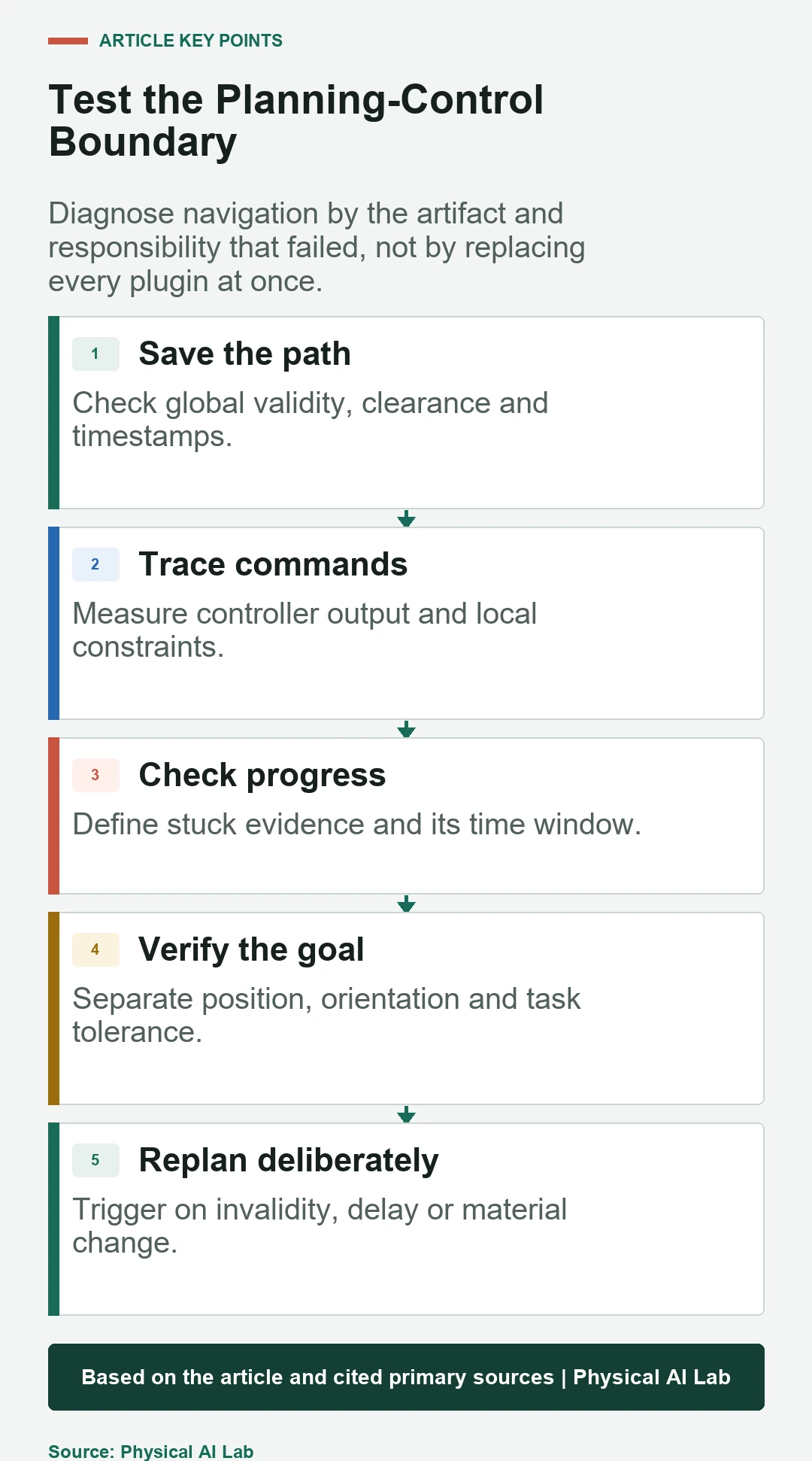
Capture goal, start pose, global and local costmaps, raw and smoothed paths, transforms, controller commands, progress state, goal state and behavior-tree result. Place them on one timeline. This chain reveals whether the wrong geometry was planned, transformed, followed or accepted.
Begin at the earliest incorrect artifact. If the path already crosses a lethal cell, controller tuning is not the first fix. If the path is valid but no command is issued, inspect local feasibility, state age and controller result before replacing the planner.
Test transitions and failure behavior
Inject a planner timeout, controller timeout, invalid path, obstacle insertion, localization jump, stale transform and command rejection. Verify cancellation and ownership when a new goal arrives. The robot should not continue following an obsolete command stream after the navigation action has failed.
Measure time from fault appearance to detection, command inhibition, recovery and final reporting. Include system load and intermittent errors because asynchronous timing often changes which component appears to fail first.
Release navigation as a measured composition
Version planner, smoother, controller, progress checker, goal checker, maps, footprints and behavior tree together. Keep scenario-level results and tail latency. Algorithm names without deployed parameters and evidence do not define a reproducible navigation system.
Use a concise release checklist for each change.
- Validate raw and smoothed paths independently.
- Measure command age, feasibility and limits.
- Test progress and goal checkers with task-specific cases.
- Control replanning frequency and path handoff.
- Trace the earliest incorrect artifact before retuning.
Frequently asked questions
Is a local controller the same as a local planner?
The term local planner is common in older ROS usage; Nav2 describes controllers that follow paths or perform local tasks and produce control effort.
How often should a global planner replan?
Use measured environment dynamics, compute time and path validity. Periodic and event-driven triggers each need bounded behavior.
Can a controller fix a bad global path?
It may avoid local obstacles within its capability, but it should not be expected to repair a globally invalid or impossible route.
Why does a robot reach the goal but not finish?
The goal checker may require position or heading tolerance the robot cannot satisfy, or it may be using inconsistent pose evidence.
What is the fastest way to diagnose a navigation failure?
Save the synchronized goal, maps, paths, transforms, commands and checker states, then find the earliest incorrect artifact.
Navigation Output and Motion Boundary
A planner path and controller command are application outputs, not safety-rated protective functions. Independent motion limits, safeguarding and stop behavior remain necessary.