When commanded torque opposes motor speed, a robot axis converts mechanical energy into electrical energy. The inverter returns that energy to the DC link. Another accelerating axis, a receptive battery, a regenerative supply or a brake resistor must accept it before bus voltage exceeds equipment limits.
Peak regenerative power and energy per deceleration are different sizing quantities. Capacitance can absorb a short pulse, while repeated or long braking needs a sustained path. The worst case often occurs with a full or cold battery, several axes braking together or a bench supply that cannot sink current.
Use this guide with the DC bus selection guide and motor sizing guide. Stop behavior and power protection require separate validation.
Follow energy from the joint into the DC link
Mechanical braking power is approximately torque times angular speed. After motor and inverter loss, the remainder enters the bus. Sign conventions matter: the same current variable may report source current as positive or negative depending on the drive.
Instrument motor speed, torque or q-axis current, DC voltage and DC current on one clock. The ODrive hardware documentation explains regenerated power and negative DC current for its products; apply each drive manufacturer’s exact definitions.

Calculate peak power and energy separately
Peak power sets instantaneous current, chopper and semiconductor stress. Integrated energy sets capacitor voltage rise, battery charge contribution and resistor pulse heating. A short high-power stop and a long descent can have equal energy but different hardware limits.
Derive both values from worst robot trajectories, payload and gravity. Include simultaneous axes and mechanical efficiency. Record how much energy remains after friction and drive loss instead of assuming all kinetic energy reaches the bus.
| Destination | Useful interval | Primary limit | Failure |
|---|---|---|---|
| DC-link capacitor | Short transient | Capacitance and voltage | Overvoltage |
| Battery | Mission scale | Charge current, SoC, temperature | BMS rejection |
| Accelerating axis | Simultaneous motion | Timing and bus current | No coincident demand |
| Regenerative supply | Continuous export | Reverse-power rating | Supply trip |
| Brake resistor | Surplus energy | Pulse, average heat and surface temperature | Overheat |
Treat DC-link capacitance as a pulse buffer
Capacitor energy rises with the square of voltage. Available absorption depends on initial bus voltage, maximum allowed voltage and effective capacitance. Parasitic inductance and wiring can create faster local spikes that a bulk calculation misses.
Measure at the drive terminals with adequate bandwidth. Check capacitor ripple current, temperature and lifetime. Do not add uncontrolled capacitance without reviewing precharge, inrush, discharge time and fault energy.
Verify whether the battery can accept charge
Battery acceptance depends on cell chemistry, state of charge, temperature, health and BMS limits. A full, cold or degraded pack may permit little regenerative current. Pack voltage can also approach the drive maximum before the BMS opens.
Use cell-level limits and coordinated torque derating. If the contactor opens during regeneration, another energy path must already exist. Test the transition rather than assuming the battery remains connected.
Reuse energy across a shared multi-axis bus
One braking joint can supply another accelerating joint on a common bus, reducing source current. The benefit depends on timing and power levels. Motion planning can improve overlap, but it cannot be the only overvoltage protection because disturbances change timing.
Log source, per-axis and resistor power to quantify reuse. Size protection for the case in which all relevant axes brake together and no consumer is present.
| Test case | Source condition | Motion condition | Acceptance evidence |
|---|---|---|---|
| Normal cycle | Mid SoC battery | Mixed axes | Voltage and energy balance |
| Full battery | Charge limited | Single hard brake | Clamp activates |
| Cold battery | Reduced acceptance | Repeated stops | No BMS trip |
| Bench supply | No reverse sink | Axis deceleration | Resistor path works |
| Emergency event | Uncertain source | Simultaneous axes | Predictable safe state |
Size brake resistance, pulse energy and cooling
A brake resistor converts surplus electrical energy into heat. Resistance must satisfy drive current and chopper limits while clamping voltage effectively. Pulse-energy rating, average power, duty cycle, enclosure temperature and safe surface placement all matter.
Use supplier pulse curves and a thermal model, then measure temperature over repeated worst cycles. Provide clearance, guarding and fire considerations appropriate to the installation. A resistor can remain hot after motion stops.
Control the brake chopper from verified bus voltage
The chopper modulates resistor duty when bus voltage or regenerated power crosses a threshold. Thresholds need margin below hardware overvoltage trips and above normal charge voltage. Measurement delay and noise affect peak clamp performance.
Test sensor bias, chopper open and short faults, disconnected resistor and saturated thermal capacity. A software enable bit is not evidence that the energy path is physically intact.
Do not assume an AC/DC supply can sink current
Many supplies deliver power but cannot absorb reverse current. Regeneration can raise output voltage or trip protection. A blocking diode can protect the source in some architectures, but then the robot needs a verified clamp or regenerative front end.
Read the supply’s reverse-power specification and test it. Avoid generalizing example voltage margins or diode choices from one drive product to a different bus and fault-current level.
Keep emergency stopping independent from efficiency
Regenerative braking can provide controlled deceleration but may become unavailable when the inverter, battery or bus is faulty. An emergency stop requires the predictable stopping architecture defined by the machine risk assessment, potentially including brakes or safe drive functions.
Test loss of bus acceptance during stop. The system must not extend stopping distance merely to protect energy-recovery efficiency. Record which mechanism produces braking torque in every fault state.
Work backward from the worst deceleration
Begin with payload, speed, height and simultaneous-axis cases. Calculate mechanical energy, predicted electrical return, source acceptance, capacitor rise and remaining resistor energy. Check semiconductor, contactor, cable and fuse stress as well as the resistor.
Repeat at minimum and maximum bus voltage, temperature and component tolerance. Tie motion limits to available absorption only when measurement, latency and fallback behavior are validated.
Test full charge, cold packs and synchronized braking
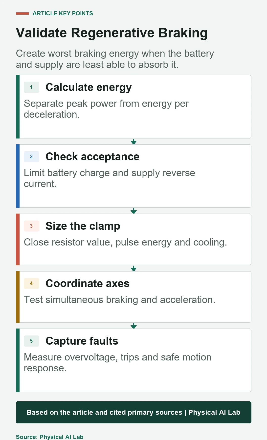
Run normal motion, hard deceleration, vertical lowering, battery-full, battery-cold, supply-only and communication-loss cases. Command simultaneous braking where credible. Measure bus peak, duration, source current, resistor temperature and protection sequence.
Inject unplugged resistor and source trip in a controlled fixture. Confirm error identity and the physical stop. Tail events matter more than average recovered energy.
Operate from voltage margin and thermal evidence
Expose maximum bus voltage, remaining margin, regenerative current, energy destination, resistor duty and temperature, plus active derating. A dashboard showing recovered watt-hours alone can hide a shrinking overvoltage margin.
Release with a testable checklist.
- Calculate power and energy for each braking case.
- Verify battery and supply reverse-current limits.
- Size capacitance, chopper and resistor together.
- Test full-charge and simultaneous-axis conditions.
- Keep safety stopping independent from energy recovery.
Frequently asked questions
Does disabling regeneration remove braking energy?
No. Mechanical energy still becomes heat, electrical bus energy or another loss and needs a controlled path.
Does a battery eliminate the need for a brake resistor?
Not always. Charge acceptance can be limited by SoC, temperature, health or BMS state.
Is the correct resistance value enough to select a brake resistor?
No. Pulse energy, average power, duty cycle, cooling, voltage and physical temperature also matter.
Can different robot axes reuse regenerative energy?
Yes on a shared bus when braking and acceleration overlap, but protection must cover the no-overlap case.
Can regenerative braking replace an emergency stop function?
No. Required stop behavior must remain valid across inverter, bus, battery and control faults.
Regenerated Energy and Stop-Function Boundary
Regenerative systems can create hazardous voltage, current and heat. Apply product-specific limits and qualified electrical, thermal and machine-safety review.