
A robot harness is an electrical network inside a moving mechanism. Conductors, shields, grounds and connectors must survive repeated bend, torsion and vibration while carrying motor power, brakes, encoders, sensors and networks. Mechanical degradation can therefore become intermittent electrical noise rather than a clean open circuit.
Harness design begins with every robot pose, not a flat wiring diagram. Define length, bend radius, twist, attachment, moving mass, thermal bundle and replacement access. Then assign power-signal separation, shield return paths, protective earth and signal reference without treating those terms as interchangeable.
Use this guide with the robot motor-driver guide and robot encoder guide. Validate the finished dress pack on the real motion and switching profile.
Treat the harness as an electromechanical subsystem
Cables add stiffness, damping, mass and reaction torque to joints. Routing can limit reach or load bearings while electrical resistance and coupling change with length and arrangement. Assign one owner for the combined mechanical, power, signal and maintainability requirements.
Create a cable inventory with conductor size, insulation, shield, pair geometry, connector, voltage, current, protocol, motion class and criticality. A replacement cable that matches pin count but not flex or impedance can introduce delayed field failures.
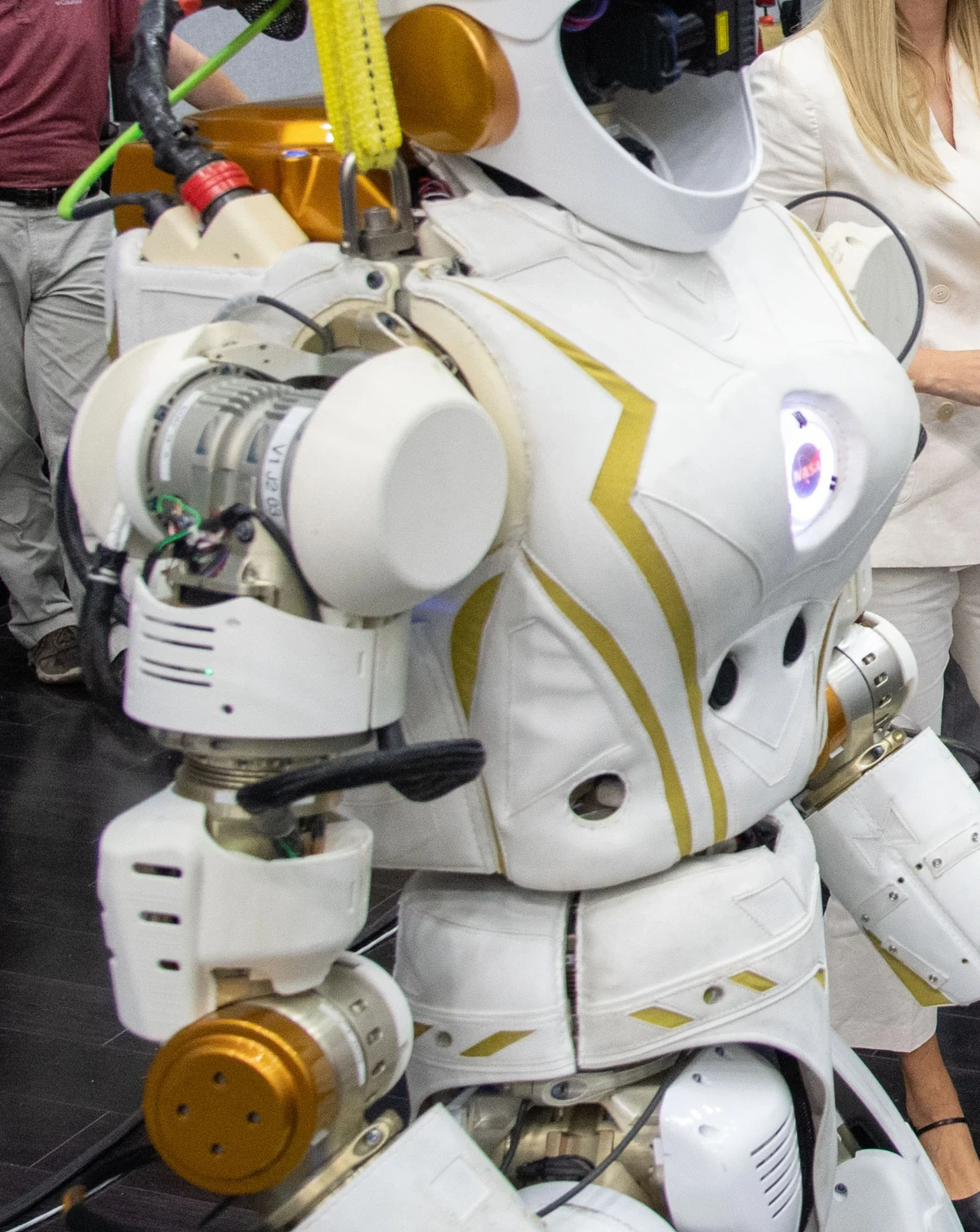
Map length and attachment through every pose
Sweep the full joint workspace including calibration, recovery and maintenance poses. Record minimum slack, maximum extension, contact points and relative motion at every clamp. Check carried tools and optional axes because they can move the first bend point.
Use physical mockups or a validated routing model, then inspect the assembled robot. A route that looks correct at zero pose may tighten at one singular configuration or rub only when two joints move together.
| Harness region | Mechanical demand | Electrical risk | First test |
|---|---|---|---|
| Fixed base | Vibration | Loose termination | Shake and torque audit |
| Cable chain | Repeated bend | Conductor or shield fatigue | Full travel cycling |
| Wrist dress pack | Bend plus torsion | Intermittent pairs | Combined-axis cycling |
| Connector exit | Localized strain | Crimp or shield break | Strain-relief inspection |
| Tool interface | Frequent service | Pin wear or mis-mate | Mate-cycle test |
Distinguish repeated bend from repeated torsion
A flex-rated cable for linear chain travel is not automatically suitable for robot torsion. Conductor lay, shield construction, jacket and allowable twist differ. Specify cycle count, bend radius, torsion angle per length, acceleration and temperature.
The igus robotic cable guidance distinguishes torsion-capable robotic cables from other motion types. Use the selected manufacturer’s data and test the assembled bundle because clamps and neighboring cables change local strain.
Keep strain away from connector terminations
Provide strain relief so the crimp, solder joint, backshell and shield bond are not the first flex point. Clamp the cable without crushing insulation or changing pair geometry. Allow controlled movement between defined supports.
Inspect pull, bend and vibration at each connector. A harness can pass conductor continuity while a shield pigtail or drain wire fractures. Record clamp position and torque in assembly instructions so service reproduces the validated geometry.
Separate switching power from sensitive signals
Motor phase leads, brake lines and DC buses carry high dv/dt or di/dt. Encoders, strain gauges and communication pairs can couple noise capacitively, inductively or through shared impedance. Maximize separation and minimize parallel runs where the architecture permits.
When routes must share a chain, use verified cable geometry, shields, differential signaling and return paths. Crossing at an angle can reduce coupling. Test worst drive switching, current and cable pose rather than only idle communications.
| Noise path | Source | Victim symptom | Control |
|---|---|---|---|
| Capacitive | Fast voltage edges | Common-mode spikes | Spacing and shield |
| Inductive | Motor and brake current | Loop-induced error | Twisted pairs and small loops |
| Shared impedance | Ground or supply return | Offset and resets | Return-path design |
| Radiated | Long cable structures | Packet or sensor error | Enclosure and termination |
| Contact intermittency | Flexed connector or shield | Pose-dependent dropout | Mechanical relief and monitoring |
Understand shielding as a current-return path
A shield intercepts electromagnetic current only when it has a low-impedance path at relevant frequencies. Long pigtails add inductance and weaken high-frequency performance. Use appropriate circumferential termination and connector shells where the system design requires it.
The correct one-end or both-end strategy depends on frequency, equipment, isolation and bonding. Avoid universal rules. Follow the system EMC plan and Siemens EMC configuration guidance alongside product instructions.
Separate protective earth, signal reference and shield bond
Protective earth provides a fault-current path under applicable electrical requirements. Signal reference establishes circuit voltage relationships. A cable shield carries coupled high-frequency currents. They may connect at planned points but do not serve identical functions.
Document bonding points, conductor sizes, expected fault paths and isolation boundaries. Measure continuity and impedance appropriately. A low DC resistance measurement alone does not prove a good high-frequency shield connection.
Expect motion to age conductors and shields differently
Fine conductors may remain continuous while foil, braid or drain connections degrade, raising coupling. Conversely, a shield may remain intact while one signal strand breaks intermittently. Connector fretting can add nonlinear resistance under vibration.
Track flex cycles, joint distribution and environmental exposure. Retest shield transfer, contact resistance, voltage drop and protocol error rate at intervals. Replace from measured degradation and criticality rather than one universal calendar.
Preserve differential-pair and termination integrity
High-speed networks and encoder links depend on controlled pair geometry, characteristic impedance, termination and common-mode range. Untwisting too far at a connector or routing different pair lengths through flex can create reflections and skew.
Verify eye quality, error counters or protocol diagnostics where available. Test startup, peak motor current and regenerative braking. Keep connector pinout, termination and shield transition in the harness drawing.
Check voltage drop and bundle temperature in motion
Current rating depends on ambient, bundling, duty cycle and moving construction. Measure voltage at the load during peak demand in the pose with longest path or hottest bundle. Repeated flex can increase contact or conductor resistance before complete failure.
Include brakes, heaters and tool power. Use thermal imaging and point sensors after heat soak, while recognizing that internal conductor temperature can exceed visible jacket temperature. Coordinate wire size with protection and connector ratings.
Cycle motion while generating electrical noise
Run representative joint trajectories while switching drives and recording continuity, voltage, shield condition, encoder errors, network retries and sensor residuals. Include cold and hot states, payload vibration and combined-axis torsion.
Inject loosened bonds or damaged samples only in a controlled fixture. Confirm that diagnostics identify degradation before unsafe loss. A stationary EMC test and a separate flex test can both pass while their combination fails.
Release drawings that capture motion and ownership
Store routing by pose, lengths, clamp locations, bend and torsion limits, connector assembly, separation classes, shield terminations, ground bonds, test limits and replacement procedure. Version the harness with robot mechanics and drive firmware.
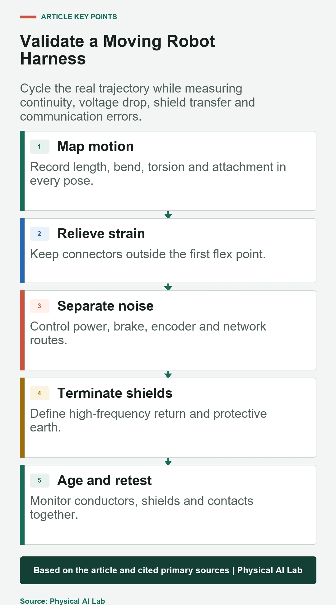
Use a release checklist.
- Map routing and strain through every valid pose.
- Specify bend and torsion life separately.
- Control power-signal coupling and return paths.
- Test shields, contacts and conductors after cycling.
- Preserve assembly geometry and service evidence.
Frequently asked questions
Can ordinary flex cable be used on a robot arm?
Only when its specified bend, torsion, acceleration, temperature and life match the actual motion; chain-flex rating alone may not cover torsion.
Should cable shields always be grounded at one end?
No universal rule applies. Frequency, isolation, bonding and product guidance determine termination.
Can motor and encoder cables share one chain?
Sometimes, with validated spacing, shielding, pair design and return paths; test the actual switching and motion case.
Why does a cable fault appear only at one pose?
That pose can maximize strain, open an intermittent strand or change coupling and contact impedance.
How should harness replacement intervals be set?
Use validated cycle life, measured degradation, environment, motion distribution and consequence of failure.
Harness Reliability and Electrical Safety Boundary
Harness and grounding design affects electrical safety, EMC and motion reliability. Apply component specifications and applicable machinery and wiring requirements.