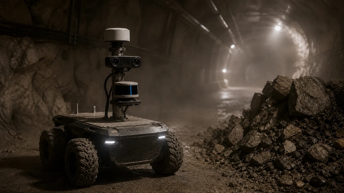
Test mmWave radar as a complementary robot sensor when the system needs independent range and closing-speed evidence through recurring darkness, glare, dust, mist or other low-visibility conditions. Do not treat it as a universal replacement: angular resolution, multipath and separation of small stationary objects can require cameras, LiDAR and task-specific fusion.
Use the Physical AI robot-sensor overview for the wider stack, the 2D versus 3D LiDAR guide for ranging geometry, the stereo, ToF and structured-light camera guide for optical depth, and robot sensor fusion for general algorithms. This page owns the radar-specific selection and validation decision.
Compare sensors against the decision the robot must make
The selection sheet starts with target size, material and speed; required range, angle and classification; lighting, dust, vapor or rain; occlusion; mounting height; and maximum processing delay. Replace a vague requirement such as ‘works in bad weather’ with the exact misses and false alarms the added sensor is supposed to reduce.
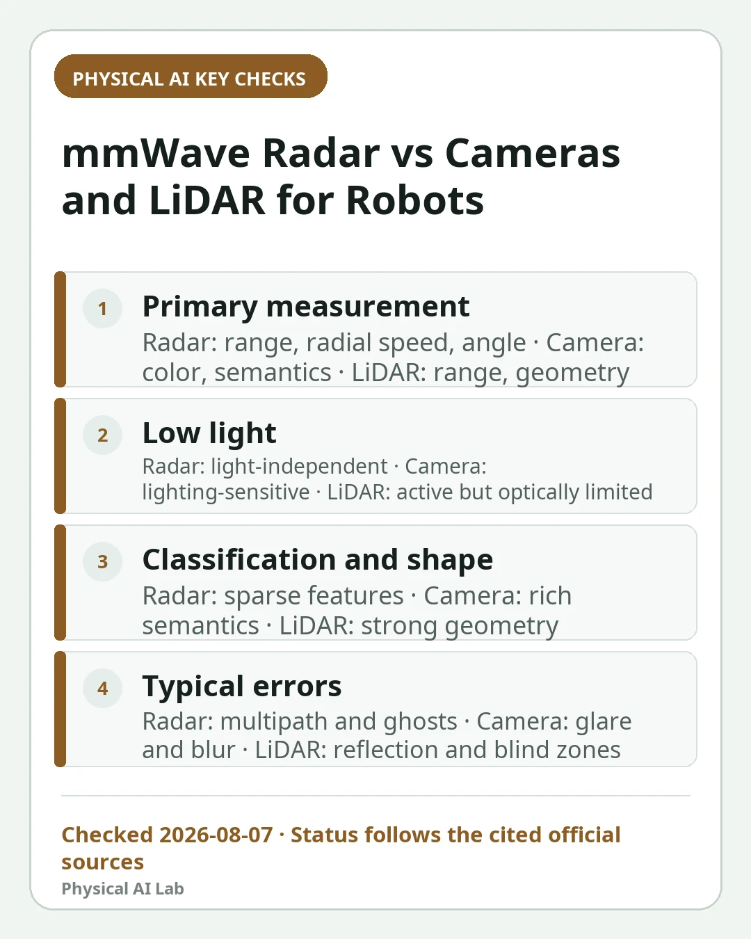
Radar's useful distinction is direct range and radial-velocity measurement. Cameras provide texture, color and rich semantic cues, while LiDAR provides geometric structure and free-space evidence. Actual performance depends on device, antenna configuration, processing, protective cover, mounting and scene.
No column wins every row. The correct architecture may use a camera for identity, LiDAR for shape and radar for independent approach speed, then keep an unmatched alert alive until the system can safely resolve it.
| Decision factor | mmWave radar | Camera | LiDAR |
|---|---|---|---|
| Primary measurement | Range, radial velocity and angle | Intensity, color and semantics | Range, geometry and reflectivity |
| Low light | Independent of visible illumination | Affected by lighting and exposure | Active ranging with optical limitations |
| Classification and shape | Sparse or processed features | Rich semantic information | Strong geometric evidence |
| Typical errors | Multipath, ghosts and angle ambiguity | Glare, blur and occlusion | Absorption, reflection, weather and blind zones |
Separate range, Doppler and angular resolution
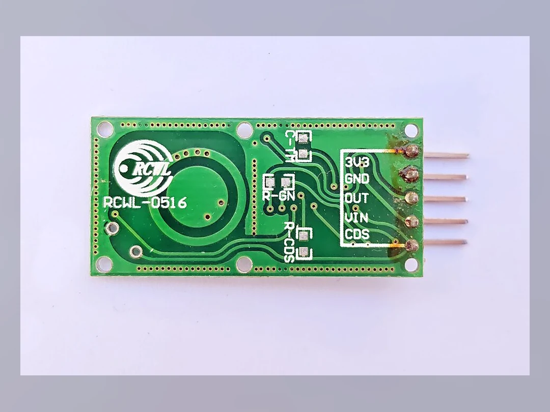
The vendor's TI mmWave radar development portal is an official starting point for sensing concepts and development resources. Define which outputs the application actually uses—range, azimuth or elevation, radial velocity, signal strength, raw detections or tracker objects—and preserve the processing configuration.
Fine range separation does not guarantee that two nearby targets can be separated by angle. Doppler reports motion along the sensor's line of sight, so lateral motion can appear differently from an approaching person. Small stationary objects can also be difficult depending on scene, geometry and filtering.
Measure each quantity with independent ground truth. A motion-capture track, surveyed reflector locations and labeled camera or LiDAR data can reveal whether an error comes from range, angle, association or a tracker that merged two detections.
Validate low-visibility claims with paired scenes
Repeat the same target trajectories under normal light, darkness, backlight or glare, airborne dust or vapor, and contamination on protective covers. Compare detection probability, false alarms, track continuity, range and velocity error, and reacquisition time with common triggers and timestamps.
The TI TIDA-010281 reference design and TI application report SWRA831A provide vendor-authored design and application material. Attribute any performance statement to its hardware, configuration and test condition, then reproduce the decision in the actual robot scene.
Include conditions in which radar is not expected to help, such as an occluded target behind a material the system cannot usefully sense or a geometry dominated by reflection. A balanced test prevents resilience claims from becoming a blanket guarantee.
.jpg)
Mounting, blind zones and multipath determine field behavior
Check radar height, tilt, field of view, chassis and arm occlusion, radome or protective cover, cable routing and vibration through the robot's full motion envelope. Map the near blind zone and the shadows created by payloads, lifting mechanisms and dock geometry along every approved route.
Multipath can place a ghost away from the real object or distort range and angle. Build separate scenes for wall corners, narrow metal aisles, glass or metal panels, a moving arm and the charging dock. Verify that an amplitude or static-clutter filter does not remove a person or a small obstacle.
A bench view with an unobstructed sensor can conceal installation failures. Run acceptance tests with final enclosure, coatings, fasteners and firmware because small mechanical or material changes can alter the observed scene and calibration.
Fuse time, frames and uncertainty before object labels
Calibrate extrinsics, coordinate frames, timestamps, latency and update rates before associating detections or tracks. When a radar track meets a camera box or LiDAR cluster, retain each covariance, occlusion state and unmatched detection so one confident sensor does not silently suppress another warning.
Choose early, feature or late decision fusion according to required failure independence and compute budget, not fashion. Health signals should detect camera glare, LiDAR contamination, radar interference and stale messages, then invoke an explicitly qualified degraded mode.
Measure association errors as their own failure class. A correct radar point attached to the wrong visual object can be more dangerous than a clean miss because it gives the fused system false confidence about identity or velocity.
Count misses, false stops and diagnostic coverage on site
Build representative routes with adults, small objects, stationary, approaching and crossing motion, partial occlusion, multiple targets, low visibility and injected sensor faults. Record per-class detection and tracking, velocity error, false stop, missed stop, operator intervention and processing p95 and p99.
The presence of radar does not confer a functional-safety integrity level. For a risk-reduction function, validate the sensing chain, fault detection, communication, compute, braking or safe stop and the diagnostic coverage required by the system safety requirements.
Keep an incident replay set and blind-zone map as release artifacts. A firmware, threshold, fusion-model or mounting change should rerun the scenes that can be affected rather than relying on a one-time demonstration.
| Test scene | Measurements | Expected fusion response | Failure action |
|---|---|---|---|
| Darkness or glare | Track, classification and latency | Radar range and speed remain available | Slow and reacquire |
| Dust or dirty cover | Sensor health, misses, false alarms | Isolate degraded sensor | Cleaning alert and safe mode |
| Metal aisle | Ghosts and angle error | Map and cross-sensor rejection | Tune zone or restrict route |
| Crossing or small stationary object | Continuity and minimum range | Preserve camera or LiDAR evidence | Cover blind zone |
Bind approval to the device, region and software version
Frequency bands, power, certification and conditions of use must be checked for the exact device and region. Do not extend a development board or reference design's compliance to a final product; antenna, enclosure, firmware and mounting changes may require engineering review and retest.
The release manifest records radar model and firmware, configuration, calibration, cover, mounting pose, fusion model, thresholds, test dataset, environment scope and known blind zones. Requalify affected scenes after a route, payload, chassis, sensor stack or software change.
Keep vendor claims clearly attributed and pair them with independent application measurements. Procurement should compare the evidence package, support and reproducibility rather than selecting a sensor solely from a range chart or a favorable demonstration.
Frequently asked questions
Can mmWave radar replace cameras and LiDAR on a robot?
Usually it is complementary. Range, radial velocity and low-light resilience are valuable, but semantic classification, precise geometry and some small stationary objects may still require other sensors.
Does radar always detect through dust or darkness?
No. Target reflectivity, angle, range, cover, interference, filtering and multipath still matter. Validate paired scenes on the actual robot and route.
Does adding radar make a perception function safety-rated?
No. Validate the complete chain from sensing and diagnostics through communication, compute, actuation and safe stop against system-level safety requirements.
Official sources checked
- TI TIDA-010281 reference design
- TI mmWave radar application report SWRA831A
- TI mmWave radar development portal
Last checked: August 7, 2026