A robot depth camera should be selected from the task volume, object surfaces, illumination, motion and required update timing. Stereo, time-of-flight and structured-light systems infer depth through different optical evidence, so each has characteristic holes, bias and interference. One published accuracy value cannot describe those conditions.
Stereo triangulates corresponding image points, ToF estimates light travel time or phase, and structured light observes deformation of a known projected pattern. Product families can combine active illumination, RGB, inertial sensors and onboard processing, which means the technology label alone is not a complete specification.
Use this guide with the robot calibration guide and robot sensor-fusion guide. Validate depth with the camera mounted on the robot and with the downstream grasping, navigation or inspection metric that will consume it.
Define the measurable task volume first
Map minimum and maximum range, horizontal and vertical field of view, robot poses, expected occlusions and required spatial resolution. A camera can cover the workspace from one pose yet lose the gripper, shelf lip or bin corners during motion. Include cable bend and protective-window constraints.
Convert the task requirement into measurable outputs: valid-depth coverage, bias, repeatability, edge localization, outlier rate and latency. A navigation system may tolerate sparse distant depth, while small-part picking can fail from millimeter-scale edge bias.

Stereo depth depends on image correspondence
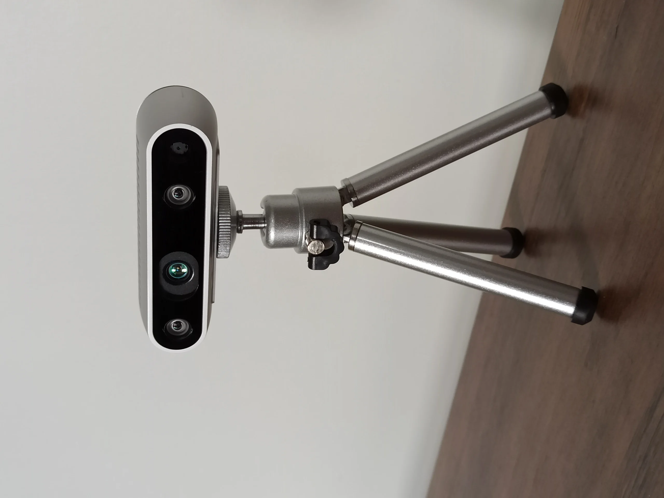
A stereo system finds matching features in left and right images and triangulates depth from disparity, focal length and baseline. Error grows with distance because the disparity difference becomes small. Texture, exposure, focus and geometric calibration directly affect correspondence.
Active stereo adds projected infrared texture for weakly textured surfaces, but strong sunlight or another projector can wash out or confuse that pattern. Passive features may still work outdoors. The RealSense D400 stereo documentation describes the product architecture; the installed robot still requires its own test.
| Method | Depth evidence | Typical strength | Typical failure |
|---|---|---|---|
| Passive stereo | Natural image disparity | Outdoor texture | Blank surfaces |
| Active stereo | Disparity plus projected texture | Indoor low texture | Sunlight or interference |
| ToF | Modulated light delay or phase | Compact dense depth | Multipath and saturation |
| Structured light | Known pattern deformation | Precise controlled scenes | Ambient light and motion |
| Sensor fusion | Multiple calibrated sources | Coverage and continuity | Time or frame error |
ToF measures active-light return timing
Time-of-flight systems illuminate a scene and estimate distance from pulse travel time or phase shift. They can produce dense depth with a compact baseline and do not need visible texture. Modulation, integration time and signal strength affect range, precision and motion behavior.
Multipath occurs when light reaches a pixel by more than one reflection, creating biased depth near corners, shiny surfaces or complex geometry. Very dark targets return little signal and reflective targets can saturate. Check confidence or amplitude channels instead of treating every numeric depth as equally valid.
Structured light observes a projected pattern
Structured-light cameras project a known spatial pattern and infer shape from its deformation. In controlled indoor conditions they can deliver detailed surface geometry useful for metrology and bin picking. The projector and camera geometry, focus and exposure must remain calibrated.
Ambient light can reduce pattern contrast, motion can distort sequential pattern acquisition, and multiple units can interfere. Industrial systems may use coded exposures and robust calibration, but cycle time and object motion must match the capture method. The current Zivid knowledge base documents one such workflow.
Surface material needs a deliberate failure map
Black materials absorb active light, glossy objects create specular reflections, and transparent objects transmit or refract light from the background. Fine metal, plastic wrap and wet surfaces can fail differently even when they share a color. Build a representative object set rather than a generic calibration target.
Mark regions as valid, uncertain, missing or physically wrong. Saving only a filtered depth map hides the failure mechanism. Preserve infrared or intensity images, confidence values and camera settings so an error can be traced to signal, correspondence or postprocessing.
| Condition | Observed symptom | Likely mechanism | Useful check |
|---|---|---|---|
| Dark surface | Holes or noisy range | Low return | Amplitude or IR image |
| Glossy surface | Flying points | Specular reflection | View-angle sweep |
| Transparent item | Background depth | Transmission or refraction | Alternate modality |
| Sunlight | Reduced active signal | Projector washout | Outdoor exposure sweep |
| Two cameras | Periodic corruption | Optical interference | Staggered capture test |
Range and field of view interact with robot pose
Minimum range can leave the gripper or close bin contents invisible, while maximum range can provide too little disparity or return signal. A wide field of view increases coverage but can reduce pixels per object and magnify edge distortion. Evaluate the exact lens and resolution mode.
Use a reach and visibility simulation as a screening tool, then measure the installed system. Robot vibration, protective glass, mount compliance and cable force can shift calibration. Include tool changes and payloads that alter the camera-to-task geometry.
Timing and synchronization complete spatial accuracy
A perfect depth frame becomes wrong when paired with a robot pose from another time. Record exposure time, transfer delay and clock relationship for depth, RGB, inertial data and joint state. Rolling shutter and sequential projection can create geometry that depends on motion within a frame.
For moving cameras or objects, test speed sweeps and abrupt direction changes. Measure end-to-end age where the planner uses the point cloud. Hardware triggering may help, but the complete timestamp and buffering path still requires validation.
Calibration includes intrinsics, extrinsics and depth scale
Intrinsics describe projection and distortion; extrinsics place the camera in a robot or world frame; depth scale maps stored values to physical distance. Temperature, impact, focus and mount changes can affect these parameters. Keep calibration identifiers with every data log.
Validate with independent geometry distributed through the task volume, not the same target poses used for fitting. Report residuals in task units and check edges as well as flat planes. A small average plane error can coexist with grasp-breaking boundary artifacts.
Postprocessing must expose rather than invent certainty
Spatial filters, temporal smoothing, hole filling and outlier removal can make depth look cleaner. They also add delay, smear motion and fill unseen regions with estimates. Tune them with downstream task evidence and preserve a validity or confidence signal.
Compare raw and filtered results during failures. A planner should know when depth is stale or unsupported. Do not convert a filled image into a safety claim; ordinary 3D cameras are not safety sensors unless the complete function has the applicable rating and validation.
Run a factorial scene test
Vary one factor at a time across distance, angle, illumination, object material, camera motion, object motion and nearby active sensors. Repeat enough times to measure variation. Include warm-up and operating temperature because projection and timing can drift.
Then combine worst factors to reproduce the deployed scene. Save settings, firmware, raw streams and task outcomes. A camera passes only if the robot meets its grasp, localization or inspection criterion with bounded failures and a defined fallback.
Treat data sheets as test hypotheses
Manufacturer ranges and precision values use stated targets, modes and environments. Orbbec’s Femto Mega page and the Zivid 3 XL250 data sheet are useful primary references, but their metrics are not interchangeable.
Record the exact firmware, exposure, emitter power, resolution and filtering configuration used in acceptance. Recheck after updates or remounting. Select from a measured failure map and lifecycle support, not from the most attractive point cloud shown in ideal lighting.
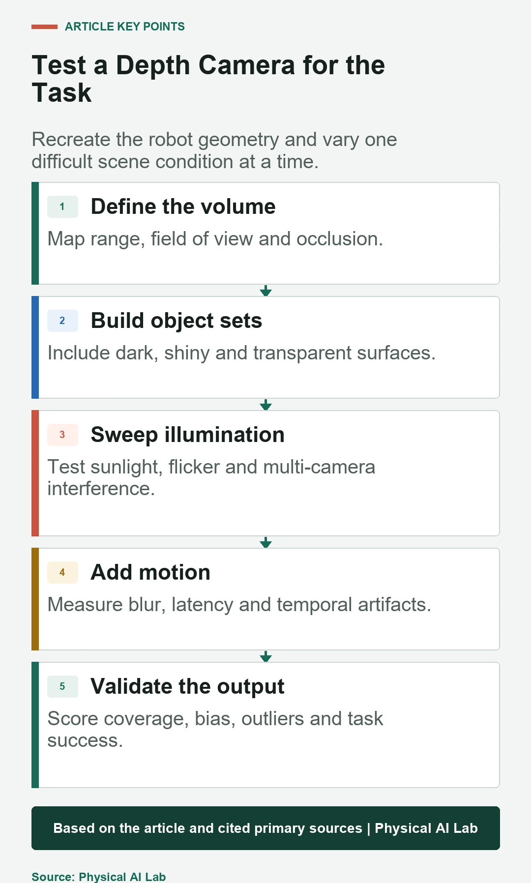
- Define the task volume and downstream metric.
- Test real dark, shiny and transparent objects.
- Measure motion, timing and synchronization.
- Validate calibration independently across the volume.
- Keep raw evidence and explicit invalid-depth handling.
Frequently asked questions
Which depth camera works best outdoors?
No method wins every outdoor scene. Strong sunlight often reduces active illumination, while passive stereo still needs texture and adequate exposure. Test the actual range and surfaces.
Is ToF always more accurate than stereo?
No. Accuracy depends on distance, signal, multipath, calibration, resolution, motion and filtering. Compare task-relevant errors under the same conditions.
Can a depth camera measure transparent objects?
Sometimes partially, but transmission and refraction often return the background or invalid geometry. Alternate lighting, views or sensing modalities may be required.
Does higher depth resolution guarantee better picking?
No. Calibration, edge quality, latency, occlusion and object-pose estimation can dominate. Evaluate grasp success and failure recovery.
Can a standard depth camera replace a safety scanner?
Not unless the complete sensing and protective function is designed, rated and validated for that safety use. Ordinary depth output is not a functional-safety claim.
Depth-Sensing Application Boundary
Depth performance depends on the exact camera mode, firmware, optics, mounting, scene and postprocessing. Validate the installed system and preserve explicit handling for missing or unreliable depth.