Turning the held part while it was still low in our Blender bin produced an obstruction at the first sampled 60-degree pose. Lifting the same closed gripper and part above the rim before turning kept every sampled pose separated. Both sequences began at the same grasp and ended at the same raised, 90-degree pose. The operation order changed the intermediate geometry.
This was an AI-operated Blender 5.2.2 LTS experiment with a rigid rectangular target, two closed fingers and a gripper body. We treated those four pieces as one carried geometric assembly. That assumption let us test envelope clearance; it did not simulate attachment, friction, gripping force or pick reliability.
The same endpoints hid different intermediate states
The bin interior was 160 mm by 100 mm, with its rim at 60 mm. The target measured 130 × 40 × 20 mm. Its centre began at 25 mm, so it was still below the rim. We compared two seven-pose sequences:
- Turn, then lift: rotate at a 25 mm centre height through 0, 30, 60 and 90 degrees, then lift at 90 degrees through 45, 65 and 85 mm.
- Lift, then turn: lift at 0 degrees through 25, 45, 65 and 85 mm, then rotate at 85 mm through 30, 60 and 90 degrees.
The independently checked finite geometry gave these results. A positive number is the smallest Euclidean distance between disjoint carried and environment solids. “Overlap” means a finite solid pair intersected; zero is not reported as a penetration depth.
| Sample | Turn before lifting | Lift before turning |
|---|---|---|
| 0 | z 25 mm, yaw 0°: 10.000 mm clear | z 25 mm, yaw 0°: 10.000 mm clear |
| 1 | z 25 mm, yaw 30°: 0.179 mm clear | z 45 mm, yaw 0°: 15.000 mm clear |
| 2 | z 25 mm, yaw 60°: target overlaps both y walls | z 65 mm, yaw 0°: 15.000 mm clear |
| 3 | z 25 mm, yaw 90°: target overlaps both y walls | z 85 mm, yaw 0°: 21.213 mm clear |
| 4 | z 45 mm, yaw 90°: target overlaps both y walls | z 85 mm, yaw 30°: 15.001 mm clear |
| 5 | z 65 mm, yaw 90°: target overlaps both y walls | z 85 mm, yaw 60°: 15.000 mm clear |
| 6 | z 85 mm, yaw 90°: 15.000 mm clear | z 85 mm, yaw 90°: 15.000 mm clear |
The table establishes the first obstruction among the sampled poses at 60 degrees. It does not locate the continuous angle at which contact would begin.
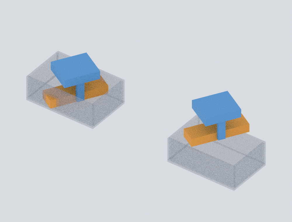
The image came from a separate CPU render with eight samples. That setting affected display quality, not the geometric measurements.
A width check explains the near miss and obstruction
Within our tested 0–90-degree range, the 130 × 40 mm target’s horizontal half-extent along the bin’s y direction is
65 sin(theta) + 20 cos(theta) millimetres.
At 30 degrees, that value is about 49.8205 mm against a 50 mm half-width, leaving the measured 0.1795 mm margin. At 60 degrees it becomes about 66.2917 mm, extending beyond both side boundaries while the target remains low enough to intersect the walls.
Height changes the classification. At a 65 mm centre height, the target bottom is 55 mm, still below the 60 mm rim; the 90-degree target therefore overlaps the side walls. At an 85 mm centre height, its bottom is 75 mm, creating 15 mm of vertical separation before the raised rotation. A planar width excess alone is not an obstruction proof when the solids are separated vertically.
Check the carried assembly, not the grasp point alone
KEYENCE describes bin-picking path planning as accounting for the robot, target and surroundings, and describes a Picking Simulator for trying different grippers and cell layouts before hardware changes. Those are vendor capability statements, not validation of this Blender result or a physical acceptance test. See the current KEYENCE 3D VGR page.
The practical lesson is narrower: after a grasp, add the held part to the collision geometry. A start pose and an acceptable final pose do not prove that an arbitrary ordering of lift and rotation is clear. Our broader bin-picking guide places this check within perception, grasp planning and collision avoidance. The robot gripper selection guide covers the larger tool-choice decision. For the separate question of whether parallel pads stay aligned during closure, see the pad-angle experiment.
What to record before accepting an extraction order
For each candidate sequence, retain the gripper, held part and environment as finite geometry in one declared frame. Record the intermediate pose, every overlapping pair and the true surface distance when solids are disjoint. Keep authored contact inside the carried assembly separate from environment obstruction.
We evaluated 14 static poses, 280 carried-to-environment pairs and 84 internal carried-body pairs. The independent check used all finite-box SAT axes for intersection and vertex-to-triangle plus edge-to-edge distances for separated solids. Its 4 micrometre corner bound and 8 micrometre comparison allowance describe numerical agreement with the authored model, not hardware accuracy or manufacturing tolerance.
This experiment did not run a robot, planner, KEYENCE system, controller or continuous collision sweep. It did not measure time, force, friction, compliance, grasp success or safety. The result supports one design action: in this declared geometry, lift before turning was the clear sampled order; validate the motion between samples and the physical grasp separately.