A robot end effector is more than payload attached to a flange. It adds moving geometry, mass and inertia, stored or supplied energy, process hazards, workpiece retention and failure modes that change the application risk and stopping behavior.
The safety boundary includes fingers, adapters, hoses, cables, valves, tool changers, racks, sensors, controllers, workpieces and nearby fixtures. Assessment covers production, exchange, setup, cleaning, jam recovery and maintenance.
This guide is educational and does not replace the applicable standard or qualified assessment. Use it with the grasp-planning guide and vacuum-gripper failure guide.
Model the complete tool boundary
List mechanics, sharp and hot surfaces, pinch spaces, energy supplies, signals, software, retained workpiece and surrounding structures. Define which tool configurations and operating modes are approved.
Draw the swept envelope including workpiece and cables. A compact wrist unit can create a large hazard after long fingers or a carried part is added.

Build a lifecycle hazard inventory
Review normal processing, tool pickup and return, calibration, setup, cleaning, jam clearing, power loss, failed release and maintenance. Many exposures occur when people approach after a production fault.
Include foreseeable wrong tool, partial engagement, worn fingers, blocked valves, lost sensing and corrupted identity. Link each scenario to a controlled response.
| Hazard source | Example | Failure consequence | Control evidence |
|---|---|---|---|
| Geometry | Pinch or sharp edge | Crush or cut | Guard and clearance |
| Dynamics | High inertia | Longer stop | Load validation |
| Process energy | Heat or rotation | Burn or laceration | Isolation and guarding |
| Retention | Vacuum or grip loss | Dropped part | Monitored hold |
| Tool change | Partial lock | Detached tool | Diverse confirmation |
Validate mass, center of gravity and inertia
Check the robot’s permitted load envelope for the exact adapter, tool, fingers, hoses and maximum workpiece. Center of gravity and inertia can violate dynamic limits before total mass exceeds nominal payload.
Update load data and verify stopping, path accuracy and braking. Incorrect load parameters can degrade both production and protective behavior.
Design workpiece behavior after energy loss
A gripper should not simply open or close by default; the safer response depends on payload, height, contact and nearby people. Define whether the part is held, lowered, supported or released in a controlled area.
Test loss of air, vacuum, electrical power and communication. Monitor pressure or vacuum where needed and account for leaks, porous parts and seal wear.
Control high-energy process tools separately
Weld guns, cutters, drills, grinders and heated tools can cause severe harm even with low robot force. Provide process-specific guarding, extraction, interlocks and energy isolation.
Do not claim PFL controls a sharp or powered tool hazard. Separate robot motion risk from process energy and verify both.
Find compound pinch and trapping points
Pinch zones form between jaws, tool and fixture, workpiece and rack, robot links and tool, and cables or hoses and structure. Their geometry changes across the path and tool state.
Inspect the full motion sequence and failure recovery, including manual movement. Eliminate or guard gaps where possible before relying on warnings.
Validate automatic tool-change engagement
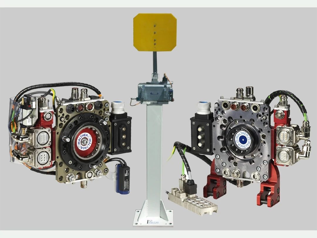
Safe exchange needs correct tool identity, mechanical engagement, energy and signal connection, and known rack state. One limit switch may fail in the same direction as an incomplete lock.
Inject wrong tool, absent tool, partial seating, contaminated interface, broken signal and lost supply. Prevent motion until the validated evidence set agrees.
Isolate stored and supplied energy for service
Commanding off is not energy isolation. Control electrical, pneumatic, hydraulic, spring, gravity, thermal and rotational energy, release stored energy and prevent unexpected restart.
Emergency stop is not a substitute for lockout or other required isolation. Provide verified procedures and accessible isolation points.
Use current guidance within scope
The ISO catalog lists ISO/TR 20218-1:2018 as published guidance for design and integration of industrial robot end effectors. It references application integration, while current project work should also consider ISO 10218-2:2025 and applicable process standards.
Consult normative texts, jurisdiction and competent professionals. This article does not establish a required architecture or conformity result.
Test failure states in the installed application
Test grip loss, dropped or jammed workpiece, wrong tool, incomplete lock, sensor disagreement, hose damage, power loss and controller timeout. Observe the physical end state, not only diagnostic bits.
Include adverse pose, load, height and human access. Verify recovery does not require unsafe reach into stored energy.
Manage wear, service and replacement
Finger wear, seals, bearings, blades, cables and couplings change retention, sharpness, balance and lock reliability. Define inspection limits, replacement intervals and functional checks.
Control replacement-part equivalence and revalidate when geometry, material, mass or software differs. Use the grasp-stability guide for changing friction assumptions.
| Gate | Test | Warning | Action |
|---|---|---|---|
| Compatibility | Load and envelope | Limit exceeded | Redesign |
| Retention | Supply-loss trial | Drop or slip | Add support |
| Tool lock | Fault injection | Single false bit | Improve evidence |
| Isolation | Stored-energy check | Unexpected motion | Revise procedure |
| Lifecycle | Wear inspection | Drift past limit | Replace and retest |
Release an approved tool configuration
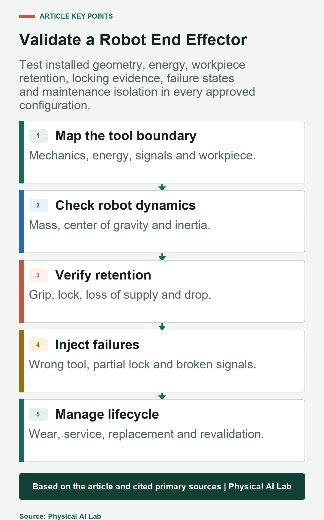
Package drawings, mass properties, energy interfaces, workpiece limits, software and identity, risk assessment, failure tests, isolation procedure, inspection criteria and change triggers. Block unapproved combinations in the controller where feasible.
Close review with the following checks.
- Include tool, workpiece and fixtures in the hazard boundary.
- Validate mass, center of gravity and inertia.
- Test retention and locking under faults.
- Provide real energy isolation and safe recovery.
- Control wear, replacement and configuration changes.
Frequently asked questions
Is any tool safe if it stays within payload?
No. Geometry, inertia, process energy, retention and interfaces also matter.
Should a pneumatic gripper always open on air loss?
No. The safer state depends on drop, crush, contact and support hazards.
Is one tool-locked signal sufficient?
Not necessarily; validate failure modes and the evidence needed for engagement and identity.
Can maintenance begin after emergency stop?
Not automatically. Required energy isolation and stored-energy control still apply.
Does changing gripper fingers require review?
Yes when geometry, force, material, mass, reach, pressure or retention changes.
Tool-Configuration and Stored-Energy Boundary
End-effectors are integrated machines with their own hazards and safety functions. Approve exact configurations only after dynamics, energy, retention, exchange, isolation and lifecycle evidence are verified.