Wheel odometry converts measured wheel rotation into an estimate of robot motion. It does not measure motion relative to the floor. Tire slip, scrubbing, deformation, uneven terrain and incorrect wheel geometry can make encoder-perfect rotation disagree with actual translation and yaw.
Calibrate wheel radius and effective track before building a slip detector. Then compare synchronized wheel motion with independent evidence such as IMU yaw rate, scan matching, visual odometry or motor current. When disagreement is credible, reduce measurement trust rather than silently forcing pose to another source.
Use this guide with the robot encoder guide and robot sensor-fusion guide. Covariance must represent tested uncertainty, not a tuning number chosen only to make a filter look smooth.
Treat wheel odometry as a model-based estimate
Encoder counts become wheel angle through resolution and gear ratio. Wheel angle becomes traveled arc through effective rolling radius. Differential or skid-steer kinematics then convert left and right motion into body translation and yaw. Error in any link enters odometry.
Before interpreting a mismatch as calibration error or slip, check how finite left/right wheel increments are integrated through a turn. The finite wheel-travel integration study contrasts the turning-arc endpoint with a straight-ahead update under the same ideal inputs. It uses AI-operated Blender geometry, not physical wheel contact, encoders, or a ROS controller test.
The model assumes a relationship between wheel contact and body motion. Longitudinal slip violates rolling distance, while lateral slip or tire scrubbing violates the nonholonomic constraint. Neither appears directly in the encoder count.
Name the motion model, feedback source, sign, timestamp and units before evaluating fusion.

Calibrate left and right rolling radius
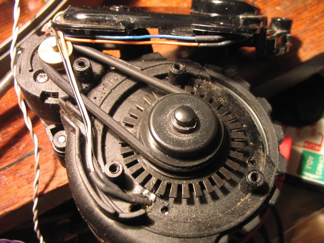
Nominal tire radius differs from effective radius under load, pressure, wear, tread and floor. Unequal left and right radii create heading drift on straight runs. Fit each side using repeated forward and reverse distances over representative payloads.
The released ROS 2 diff_drive_controller documentation exposes wheel radius and side-specific radius multipliers. Use measured parameters and held-out validation rather than copying defaults.
| Parameter | Primary symptom | Calibration motion | Confounder |
|---|---|---|---|
| Common radius | Distance scale error | Long straight runs | Slip and tire load |
| Radius mismatch | Straight heading drift | Forward and reverse | Floor slope |
| Effective track | Turn-angle error | Large bidirectional turns | Scrubbing |
| Encoder scale | Distance and speed gain | Reference rotation | Gear ratio |
| Time offset | Acceleration residual | Timed maneuvers | Filter delay |
Identify effective track during turning
For ideal differential drive, wheel separation maps speed difference to yaw rate. Real skid-steer vehicles scrub tires laterally, so an effective track can differ from physical spacing and vary with speed, surface and payload.
Fit turns in both directions and at several rates. If one constant cannot explain the envelope, use a validated state-dependent model or reflect the residual in covariance and speed limits.
Publish pose and twist in the correct frames
The official ROS Odometry message definition states that pose is expressed in header.frame_id while twist is expressed in child_frame_id. Mixing these semantics corrupts fusion even if numbers look plausible.
Follow the intended map, odom and base relationship described by REP 105. Wheel odometry normally supports a continuous local odom frame; global corrections belong in a separate transform.
Detect longitudinal and lateral slip from context
Hard acceleration or braking can spin or skid drive wheels. Tight turns on high-friction floors can create lateral scrubbing, while thresholds, ramps, debris or low-friction patches can cause brief discontinuities. Skid-steer motion contains expected slip even during normal control.
Classify events by commanded acceleration, wheel speeds, IMU rate, motor current and environment. A single encoder residual threshold cannot distinguish calibration error, timestamp error and physical slip.
Build residuals with independent measurements
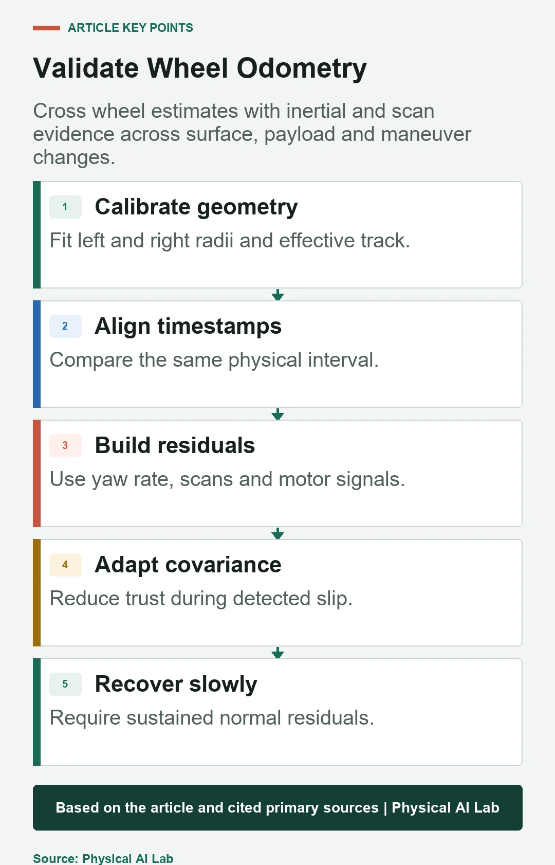
Compare wheel-derived yaw rate with calibrated IMU yaw rate and wheel translation with scan, visual or external velocity. The comparisons must refer to the same frame and physical interval. Different filtering delays can create false slip during acceleration.
Use the IMU calibration guide for inertial uncertainty. A second source is useful only when its own health and failure modes are tracked.
| Residual | Slip evidence | Alternative cause | Cross-check |
|---|---|---|---|
| Wheel yaw minus IMU yaw | Turning scrub or wheel slip | Gyro bias or time offset | Scan rotation |
| Wheel speed minus scan speed | Drive slip | Scan-match failure | Motor current and IMU |
| Left-right asymmetry | One-wheel traction loss | Radius mismatch | Surface and current |
| Pose innovation spike | Odometry fault | Global sensor outlier | Multi-source gating |
| Sustained small bias | Calibration drift | Floor slope or payload | Bidirectional route |
Increase covariance before changing the estimate
When evidence indicates slip, the wheel measurement has become less reliable. Increase the relevant pose or twist covariance so a fusion estimator can reduce its weight. Direction matters: longitudinal, lateral and yaw uncertainty need not grow equally.
Do not edit history or snap odom pose to a global source in the wheel driver. That can create a discontinuity that violates the frame contract and destabilizes controllers.
Avoid fusing duplicate encoder information twice
Pose increments and twist calculated from the same encoder counts are correlated. Feeding both as independent measurements can make a filter overconfident. Decide which variables carry unique evidence and account for correlation where the estimator supports it.
The robot_localization project provides nonlinear state-estimation nodes, but correct configuration still requires sensor semantics, covariance and frame discipline.
Recover trust with hysteresis and sustained evidence
A detector that instantly restores low covariance when one residual falls below threshold can chatter during intermittent traction. Require a dwell time, several independent normal residuals or a state-machine transition before confidence returns.
Keep recovery slower than detection where the risk favors caution. Log the reason, start, maximum severity and recovery condition for every event.
Account for timestamp and filtering latency
Encoder counters, drive feedback, IMU and scan matching may use different clocks and filter windows. Comparing a current wheel rate with a delayed scan velocity creates an acceleration-shaped residual that resembles slip.
Verify acquisition timestamps and transport delay with the robot timing workflow. Align signals before fitting thresholds or covariance models.
Validate across maneuvers, floors and payloads
Test straight motion, large and tight turns, acceleration, braking, thresholds, ramps, wet or dusty patches and payload extremes. Use independent trajectory or velocity ground truth where practical. Separate systematic scale error from event-driven slip.
Evaluate trajectory error, residual distributions, detector precision and recall, covariance consistency, recovery time and downstream navigation. A smooth fused path can still be statistically overconfident.
Operate with raw evidence and a clear fault policy
Record encoder counts, wheel states, commands, motor current, IMU, comparison source, residuals, covariance mode and timestamps. Preserve enough raw evidence to replay an event without relying on the final pose alone.
Release with a concise checklist.
- Calibrate wheel radii and effective track first.
- Align frames, clocks and filter delays.
- Detect slip from multiple independent residuals.
- Adapt directional covariance without snapping odom.
- Validate detection, recovery and fusion consistency on real surfaces.
Frequently asked questions
Can wheel-odometry covariance be zero?
No practical wheel estimate is exact. Publish uncertainty supported by data; zero values can also be interpreted unexpectedly by consumers.
Can an IMU detect every wheel-slip event?
No. It adds independent angular and acceleration evidence but has bias, noise and weak sensitivity during some steady motions.
Is effective track always the physical wheel spacing?
Not for many skid-steer systems. Tire scrubbing can make the kinematic value depend on surface, speed and load.
Should global SLAM pose overwrite odom during slip?
Normally no. Keep odom continuous and apply global correction through the intended map-to-odom relationship.
Is measuring wheel radius with a ruler sufficient?
It is an initial value. Calibrate effective rolling radius from driven distance under representative load and surface conditions.
Motion Estimate and Fusion Boundary
Adaptive covariance is not a substitute for traction control, mechanical repair or an appropriate safety function. Validate estimator and robot response together.