A selective pallet head needs two geometric checks at once: its intended faces must engage the marked block, and its complete body must remain clear of every member that stays in the pallet. Full projected overlap with the target is insufficient. In this Blender study, a wider head covered both target patches while leaving a gap at each face. A lateral offset retained the same projection but introduced target penetration and three separate collisions with retained members.
This is Physical AI Lab’s AI-assisted virtual assembly experiment, built and measured in Blender 5.2.2 LTS in October 2026. We captured actual evaluated geometry and independently checked its finite surfaces. It is a study of four static configurations, rather than a physical pallet-repair trial.
The practical consequence is to keep target engagement and neighbor clearance as separate results. Adjusting a jaw until it looks aligned can conceal a back plate catching a nearby support. Checking only the jaws can miss that failure even when the intended target is correctly identified.
Keep the marked block inside a complete pallet model
The useful starting point is a designated member, not a simplified opening around it. The model used one connected generic pallet coupon containing ten closed box members: two stringers, three deck boards, four retained supports, and one marked block. The marked block stayed in its fitted position throughout the study. The other nine members defined what the head had to avoid.
The second connected core was a five-member head: a back plate, two arms, and two inward-facing tabs. All five members moved together with a prescribed rigid pose. Different jaw widths were authored as separate static configurations; the study did not simulate a mechanism adjusting its jaws.
The marked block was 18 mm across in the lateral direction. Each of its opposed side faces carried an authored 8 by 6 mm capture patch, an area of 48 mm². These patches were finite measurement regions on the block faces, not holes, damage detections, or vendor-supplied gripping features. The wider head had a 20 mm inner gap; the narrower configuration used 18 mm.
Same-core members deliberately overlapped to form connected rigid solids. Those overlaps provided a generic assembly relation; they did not reproduce timber joints, nails, or the mechanics of an actual pallet. Every dimension and head shape belonged to this explanatory model.
The industrial motivation comes from Yaskawa’s Pallet Repair Systems description, checked on 11 October 2026. It describes an operator selecting damaged pallet members on a touch screen for hydraulic dismantling. It does not supply the head geometry or capture criteria used here.
The following bounds reproduce the authored geometry before each head translation. Coordinates are millimetres in each cell’s local frame; Blender coordinates use metres. In the support row, instantiate all four combinations of x = −35 or +35 and y = −22 or +22 mm. For the head, s is 10 mm in the wider configuration and 9 mm in the narrower one.
| Closed member | X bounds, mm | Y bounds, mm | Z bounds, mm |
|---|---|---|---|
| Two stringers | −55 to 55 | −27 to −17; 17 to 27 | 10 to 18 |
| Three deck boards | −47 to −33; −7 to 7; 33 to 47 | −40 to 40 | 17 to 22 |
| Four retained supports | x − 9 to x + 9 | y − 5 to y + 5 | 0 to 11 |
| Marked block | −9 to 9 | −9 to 9 | 8 to 18 |
| Head back plate | −28 to −24 | −s − 6 to s + 6 | 10 to 16 |
| Negative-side arm | −24.5 to 4 | −s − 6 to −s − 1.5 | 10 to 16 |
| Positive-side arm | −24.5 to 4 | s + 1.5 to s + 6 | 10 to 16 |
| Negative-side tab | −4 to 4 | −s − 2 to −s | 10 to 16 |
| Positive-side tab | −4 to 4 | s to s + 2 | 10 to 16 |
The target patches occupy X = −4 to +4 and Z = 10 to 16 mm on the block’s Y = −9 and +9 mm faces. The block shares a small positive-volume connection with the central deck board, just as the generic supports and stringers connect within their core. That geometric union defines membership; it does not model the block’s nails or a releasable wood joint.
A full patch projection can still miss contact
The four configurations changed axial position, lateral alignment, or head width while preserving the same target. The approach configuration placed the whole head 12 mm back along the model’s X axis. The wider aligned head used the nominal axial position. The offset case translated that wider head 3 mm along Y. The narrower case returned to the aligned pose with an 18 mm inner gap.
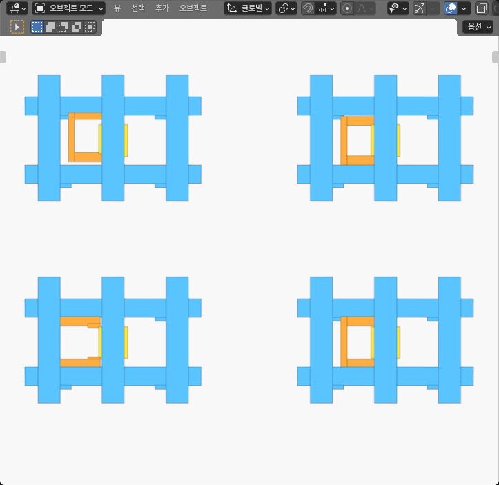
The measurements came from the Blender model’s evaluated finite geometry. Each configuration included the whole pallet and head, rather than an isolated capture face. Across the four cells, the model contains 60 closed meshes, 480 evaluated WORLD vertices and 720 native triangles. Three complete geometry reads retained every member. The side-by-side cell offsets arrange the examples for display; they are removed from the target-relative measurements.
| Configuration | Projection over both target patches | Signed face gaps, negative / positive side | Complete head versus retained members |
|---|---|---|---|
| Wider head, approach position | Incomplete | About +1 / +1 mm | Disjoint; minimum distance about 1 mm |
| Wider head, aligned | Full | About +1 / +1 mm | Disjoint; minimum distance about 1 mm |
| Wider head, 3 mm lateral offset | Full | About -2 / +4 mm | Three positive-volume intersections |
| Narrower head, aligned | Full | Zero within the numerical comparison band | Disjoint; minimum distance about 1 mm |
The approach sample had approximately zero projected patch overlap on either side. The other three configurations covered approximately 48 mm² on each side. Full coverage was checked against the complete finite patch boundary, rather than accepted from area alone.
Here, projection means the overlap of a head face with its corresponding finite target patch in the block’s local frame. It does not mean overlap between colored shapes in the screenshot. The two facing surfaces must also have opposed normals and the required separation.
The wider aligned head illustrates the difference. Both faces projected over the complete patches, yet each remained about 1 mm away from its target side face. The projection answered whether the face covered the intended region. The positive gap answered whether it had reached that region. Those are different questions.
The narrower aligned configuration met both authored patch relations within the coordinate comparison band. Its reconstructed gap intervals spanned approximately -0.00802 to +0.00802 mm. Calling this geometric contact uses the fixed 8 micrometre comparison allowance plus a 20 nanometre arithmetic reserve. These numerical allowances do not establish a woodworking tolerance, a usable gripping clearance, or physical contact force.
This distinction also appears in the slide-gate aperture overlap study: a projected area answers a particular geometric question. It needs interpretation before it becomes a claim about how a mechanism behaves.
The offset catches a support behind the apparent target
Moving the wider head laterally preserved full projection over both target patches. One face instead passed about 2 mm beyond its target plane, while the opposite face sat about 4 mm away. Full projected area therefore coexisted with penetration on one side and separation on the other.
The complete-head check found three retained-member intersections:
- The back plate intersected the positive-side stringer.
- The back plate also intersected the retained support on that side at the negative-X position.
- The positive-side arm intersected the positive-side stringer.
The back plate and support pair matters because it sits outside the two intended capture faces. A jaw-only check would omit it. Reviewing a plausible-looking target relation cannot compensate for leaving that piece of the head out of the model.
Target solid intersections were recorded separately. In the offset configuration, the negative-side arm and tab penetrated the marked block. They were not counted as retained-member collisions, because the block was the selected target. They still prevented treating the pose as the intended pair of face contacts. Selecting a member for engagement does not make every head-to-target penetration acceptable.
Across the four configurations, the analysis considered all five head members against all nine retained pallet members: 45 pairs per configuration, or 180 overall. It also checked the five head members against the target, giving 20 additional pairs. This complete enumeration is the reason the small back-plate/support collision stayed visible in the result.
Compare the two relations before choosing a pose
For a similar Blender study, begin by separating intended target relations from forbidden relations to retained members. Then use the same complete head geometry in both checks.
- Recover the target-relative pose. Express the head’s evaluated vertices and faces in a datum tied to the marked block. Remove any display offsets used to arrange comparison cells. Object names and an apparently centered origin are not enough to establish the relation.
- Define finite capture regions. Identify the two block-side patches and the corresponding complete head faces. Check projected overlap, opposing face normals, and signed plane separation for each side. Keep the two results separate until both meet the authored criterion.
- Check the whole head against the retained pallet. Include the back plate and both arms as well as the tabs. Enumerate every head-to-retained-member pair; distinguish a strictly positive solid intersection from a separated pair with a small distance.
- Review head-to-target relations separately. Verify that the intended face relations do not conceal an arm or tab passing through the marked block. Target selection identifies the intended member, not an exemption from geometry checks.
When several intended interfaces must agree with one rigid head pose, the dual-pickup-head closure study develops that adjacent question. Here, the additional requirement is to exclude the rest of the same workpiece from the complete head envelope.
Engagement is the start of a removal question
The narrower aligned configuration satisfied this model’s static geometric engagement check: both finite patch relations agreed, and the complete head remained disjoint from the retained members. That result identifies a pose worth studying further. It does not show that the marked block can be pulled out.
The four cells were independently authored snapshots. They did not test continuous entry, an extraction trajectory, jaw actuation, friction, grip force, wood deformation, nail release, hydraulic loading, or retained-member survival. No robot, vision system, physical pallet, or product performance was tested.
If the next design question is removal, the next model must include the proposed motion and the constraints that persist during it. The wooden-key joint release-direction study shows why a common release direction is a separate question from a fitted static state.
For this engagement problem, choose a configuration only after the intended finite target relations and complete-head neighbor clearance agree. Preserve those two results as you move to a path or force study; neither a full projection nor an attractive static pose can stand in for the next experiment.