A robot actuator is the joint subsystem that converts electrical energy into controlled mechanical motion. It usually contains a motor, transmission or direct-drive connection, bearings, encoders, power electronics, structure and wiring. Many designs also include torque sensing, a holding brake, temperature sensors and local control firmware.
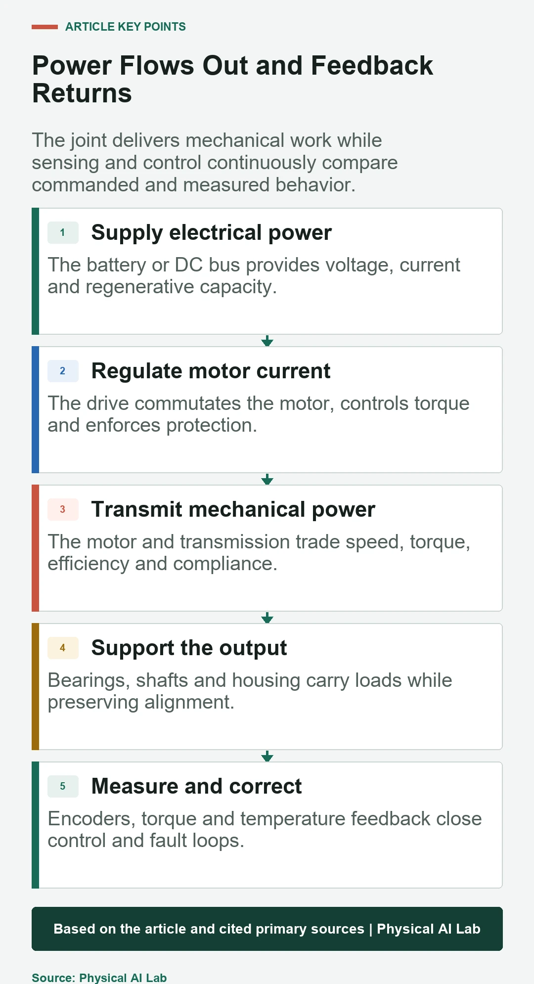
Understanding the structure means tracing two paths. The power path runs from the battery or DC bus through the drive and motor to the transmission and output link. The feedback path runs from current, position, torque and temperature sensors into control software that regulates motion and detects faults.
This component-level guide supports the industry view in humanoid actuator suppliers and the system view in Physical AI control. Exact architectures differ by joint, but the engineering questions remain consistent.
The motor converts current into torque
Brushless permanent-magnet motors are common in modern electric robots. The stator produces a rotating magnetic field and the rotor follows, creating torque. Motor geometry, winding, magnets, air gap and cooling determine the torque-speed and thermal envelope.
Frameless motors integrate directly into a custom housing, while housed motors provide a more complete component. Compare phase resistance, torque constant, back EMF, rotor inertia, voltage and continuous temperature. Current creates torque but also copper loss, so sustained output is a thermal question.
The transmission changes torque, speed and compliance
A reducer lets a smaller, faster motor produce higher joint torque. Harmonic, planetary, cycloidal, belt and cable transmissions differ in ratio, efficiency, backlash, stiffness and shock behavior. Direct and quasi-direct drive reduce the ratio to improve transparency and bandwidth.
Transmission choice changes control. Friction can hide small forces, backlash creates lost motion and elasticity stores energy. Model these effects and measure them at the output shaft. A motor-side encoder cannot directly observe every transmission error.
| Architecture | Main benefit | Primary tradeoff | Typical fit |
|---|---|---|---|
| High-ratio reducer | Compact output torque | Friction and reduced backdrivability | Heavy load joints |
| Planetary | Efficient compact stages | Backlash and stage complexity | General rotary joints |
| Belt or cable | Remote or compliant routing | Tension and wear | Research or lightweight joints |
| Quasi-direct drive | Transparency and bandwidth | Larger motor current | Dynamic legs and arms |
The open actuator makes the power path visible
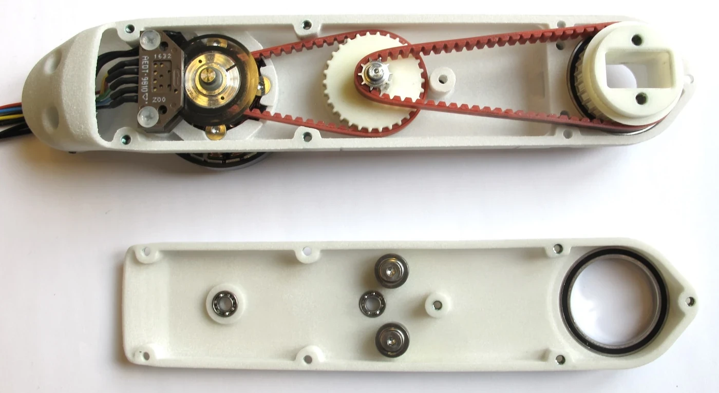
The Open Dynamic Robot Initiative module shows a motor and optical encoder connected through two belt stages to an output shaft supported by bearings. Its exposed construction helps identify transmission and feedback components that are hidden inside a sealed commercial joint.
The example should not be copied without context. A humanoid joint may use a compact reducer, dual encoders, torque sensor, brake and integrated drive. The correct structure depends on motion range, load, impact, environment, service and manufacturing volume.
Bearings carry loads and locate the output
Bearings support radial, axial and moment loads while maintaining alignment. Preload reduces play but increases friction and assembly sensitivity. The output bearing arrangement can dominate joint stiffness and life even when the reducer has sufficient torque capacity.
Calculate load across the full robot posture and include impacts. Housing tolerances, thermal expansion, lubrication and contamination affect bearing behavior. Test runout, friction and stiffness after assembly rather than relying only on individual bearing ratings.
Encoders observe rotor and joint position
Motor encoders support commutation and high-rate control. Output encoders measure joint motion after the transmission and expose some backlash, compliance or slip. Absolute encoders retain position across power cycles, while incremental devices need a reference procedure.
Resolution is not the same as system accuracy. Mounting eccentricity, interpolation, temperature, alignment and structural deflection create error. Calibrate the installed joint and store offsets with hardware identity.
Torque sensing improves interaction control
A strain-based torque sensor measures deformation in the joint load path. Current-based torque estimation uses motor current and a model but includes friction and transmission uncertainty. Series elastic actuators infer force from a deliberately compliant element.
Choose range, overload, noise, drift and bandwidth for the task. Fine manipulation needs sensitivity, while leg joints face large impacts. Torque feedback can support compliance and collision detection, but safety decisions still require validated thresholds and fault handling.
| Feedback | Measures | Advantage | Blind spot |
|---|---|---|---|
| Motor encoder | Rotor position | Fast commutation and control | Transmission error |
| Output encoder | Joint position | Observes post-reducer motion | No direct contact force |
| Motor current | Estimated motor torque | Uses existing drive sensing | Friction and calibration |
| Joint torque sensor | Output load | Interaction and compliance | Overload and drift |
| Temperature | Thermal state | Protects sustained operation | Sensor location lag |
The drive regulates electrical power
The motor drive measures current and rotor position, switches the DC bus and closes current or torque loops. The ODrive control documentation is one public example of position, velocity and torque control modes. A production drive must also enforce voltage, current and temperature limits and report faults.
Drive placement affects heat, cable mass, EMI and service. Regenerative motion returns energy to the bus and can raise voltage if the system cannot absorb it. Power design must include braking, battery behavior and simultaneous motion across many joints.
Brakes and mechanical stops manage unpowered states
A holding brake can prevent a gravity-loaded joint from falling when power is removed. It may not be designed to stop full-speed motion repeatedly. Mechanical stops protect travel limits but can transmit severe impact into gears and housing.
Define brake release timing, residual torque, wear, diagnostic coverage and safe lowering procedures. A robot should not assume every joint remains supported after a power fault. System-level safe stop and recovery planning must account for pose and payload.
Housing and thermal paths complete the actuator
The housing locates bearings, maintains air gaps, transfers joint loads and conducts heat. It also protects cables and sensors while fitting the robot’s structure. Reducing mass can lower stiffness or cooling margin, so topology and material choices need coupled analysis.
Map heat from windings, electronics, bearings and transmission to surfaces and coolant or airflow. Validate at ambient extremes and representative duty cycles. Temperature limits may require dynamic torque derating rather than a single maximum rating.
A joint test should isolate every layer
Measure no-load friction, torque-speed efficiency, backlash, stiffness, position accuracy, control bandwidth, thermal rise, noise and overload response. Use calibrated output torque and position references. Repeat tests across temperature, bus voltage and assembly samples.
Log current, motor and output position, torque, temperature, commands and faults on a common clock. This reveals whether error begins in the drive, motor, transmission, structure or sensing. Preserve serial-number calibration and test results for field diagnosis.
- Trace electrical and mechanical power paths.
- Measure output rather than motor-only performance.
- Separate motor and joint position feedback.
- Test sustained thermal and regeneration behavior.
- Validate faults, brakes and safe unpowered states.
Frequently asked questions
Is a robot actuator just a motor?
No. A joint actuator usually includes transmission, bearings, sensing, drive electronics, housing, wiring and often a brake or torque sensor.
Why do robot joints use reducers?
Reducers multiply torque and reduce speed, allowing a smaller motor to drive a load. They also introduce friction, backlash, compliance and impact limits.
Why use two encoders in one joint?
A motor encoder supports commutation and fast control, while an output encoder measures post-transmission position and can reveal backlash or elastic deflection.
Does every joint need a torque sensor?
No. Some estimate torque from motor current or use external force sensing. Direct torque measurement is valuable when interaction, compliance or accurate load feedback justifies the cost and complexity.
What limits continuous actuator torque?
Continuous torque is usually limited by heat, efficiency, cooling, winding temperature, drive current and transmission capacity under the actual duty cycle.
Mechanical and Control Note
Actuator architectures and ratings vary widely. Verify current component datasheets and measure the complete assembled joint under representative loads, temperatures, motion and fault conditions.