A robot reducer converts a motor’s relatively high speed and low torque into the slower, higher-torque output required by a joint. Strain-wave, cycloidal and planetary reducers can all perform that job, but their internal geometry creates different behavior in backlash, stiffness, friction, efficiency, shock loading and packaging.
The correct comparison starts at the joint output. Peak catalog torque alone does not describe repeated reversals, walking impacts, low-speed force control, thermal loss or lifetime. Bearings, housing, lubrication, alignment and control can change the result after the reducer enters a complete actuator.
Use this guide with the robot actuator structure guide and frameless motor integration guide. It explains selection logic; the supplier’s current ratings and joint-level tests remain authoritative for a design.
A reducer changes more than torque and speed
An ideal ratio multiplies motor torque and divides speed. A real reducer also adds inertia, friction, compliance, lost motion, heat and limits on radial, axial and moment loads. These effects enter position control, torque estimation, energy use and contact behavior.
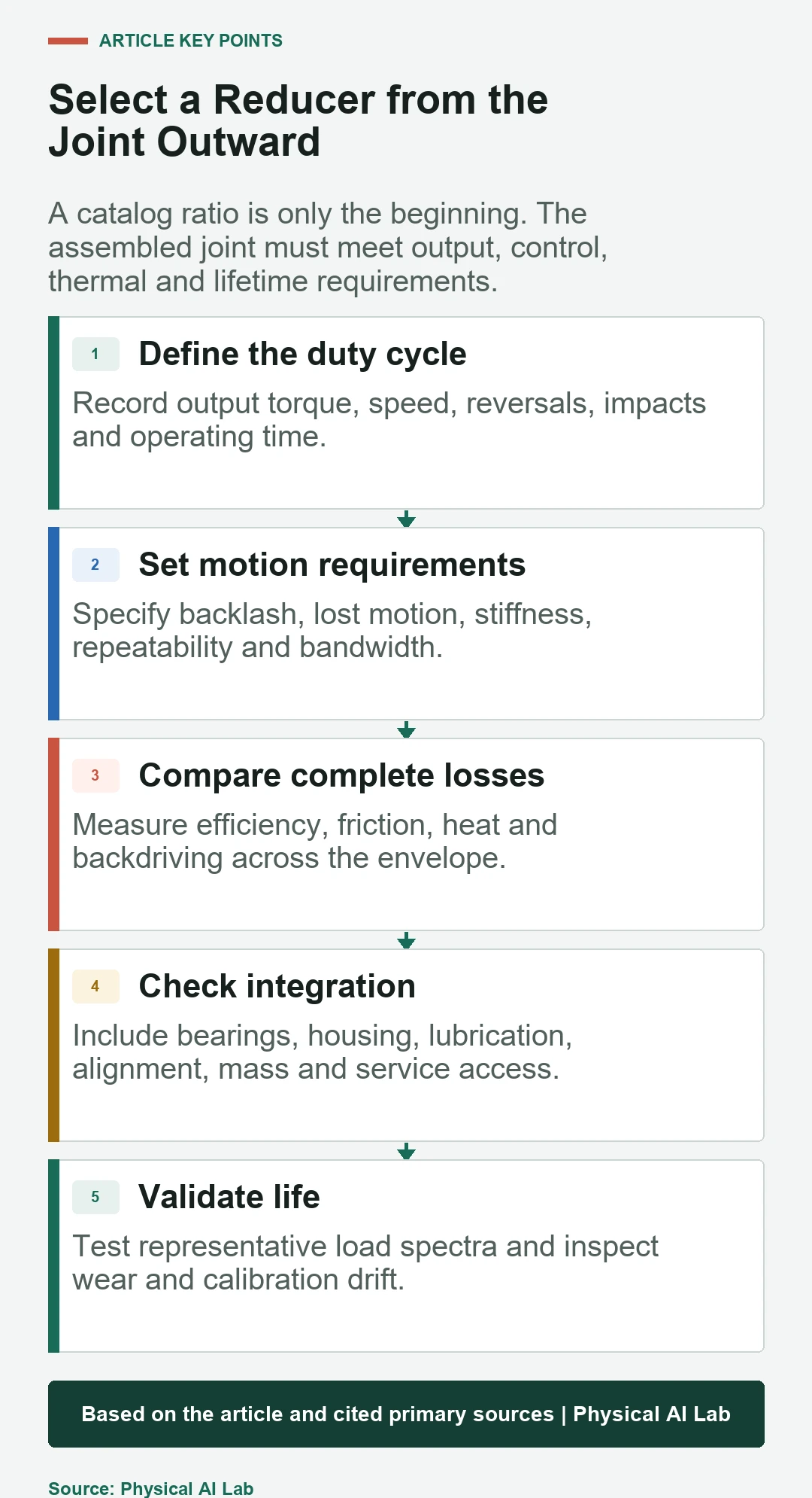
Define continuous and peak output torque, speed, acceleration, reversals, duty cycle and expected impacts. Add motion requirements such as positioning accuracy, repeatability, stiffness and low-speed smoothness. The reducer should be evaluated inside this complete operating envelope.
Strain-wave reducers package high ratio in a compact form
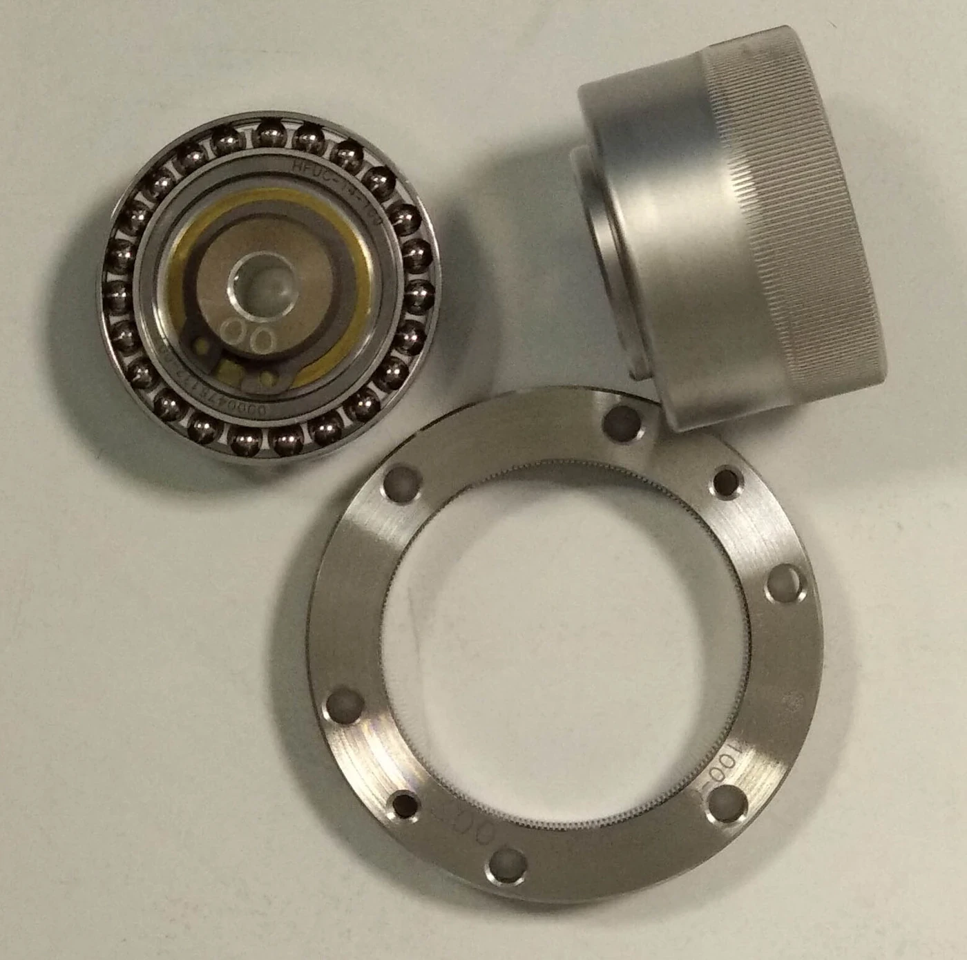
The Harmonic Drive technology overview describes the wave generator, flexible spline and circular spline. Elastic deformation creates many simultaneous tooth contacts and a high ratio in a compact coaxial package.
This architecture is widely associated with low backlash and compact joints. The flexing element, lubrication, load distribution and bearing arrangement still impose fatigue, stiffness, friction and overload constraints. Zero-backlash language should not be interpreted as zero compliance or zero lost motion under load.

Cycloidal reducers distribute load through pins and lobes
Cycloidal reducers use an eccentric input and lobed discs that engage pins or rollers. The Nabtesco precision reducer overview shows an industrial implementation with integrated bearings and high rigidity intended for robot joints.
Multiple contact regions and robust geometry can support high loads and impacts. Tradeoffs include part count, eccentric dynamics, manufacturing precision and package shape. Compare torque density only when bearings, output flange and housing are included consistently.
Planetary reducers offer modular stages and broad availability
Planetary stages share load among planet gears around a sun gear. Designers can combine stages for ratio and use familiar gears, bearings and manufacturing processes. Efficiency can be strong, especially at moderate ratios, and the architecture is available across many sizes.
Backlash, stage count, carrier stiffness, bearing support and lubrication determine installed behavior. Precision planetary units are not equivalent to general-purpose gearboxes. A multi-stage design may increase length, inertia and error accumulation while meeting ratio targets.
| Reducer family | Typical strength | Critical tradeoff | Check at joint level |
|---|---|---|---|
| Strain-wave | Compact high ratio and low backlash | Elasticity, friction and flexspline fatigue | Lost motion, stiffness and overload |
| Cycloidal | Rigidity and impact capacity | Complex eccentric mechanism | Ripple, bearings and package mass |
| Planetary | Efficiency and modular staging | Backlash and stage accumulation | Carrier stiffness and repeatability |
| Belt or cable | Remote routing and compliance options | Tension, wear and package volume | Slip, service and thermal behavior |
Backlash, lost motion and stiffness are separate quantities
Backlash is free movement caused by clearances when torque reverses. Lost motion can include backlash plus elastic hysteresis and friction. Torsional stiffness describes the change in angle under load. A reducer can have little free play yet deflect measurably under torque.
Measure output angle against torque through both directions and across relevant temperatures. Use the actual mounting, preload and lubrication. The resulting hysteresis curve is more useful to control engineers than one isolated arc-minute value.
Efficiency and backdrivability shape robot interaction
Efficiency varies with speed, torque, temperature and direction. Seal drag and lubricant behavior can dominate at light load, while tooth and bearing losses grow elsewhere. Low efficiency produces heat and changes the battery energy required for repetitive tasks.
Backdrivability depends on ratio, friction, motor cogging and joint inertia, not the reducer label alone. A transparent joint can improve force control and safe interaction, while a high-ratio joint may hold load with less motor current. Measure the complete actuator.
Impact and overload require explicit load cases
Walking, catching a payload and hitting a mechanical stop create short loads that differ from steady torque. Catalog emergency or momentary ratings use specific assumptions. Repeated overloads can damage teeth, the flexspline, bearings, lubricant or output structure even if the joint still moves.
Build a load spectrum from simulation and hardware logs. Include torque direction, speed at impact and support from neighboring joints. Inspect wear, backlash, noise and efficiency after testing instead of declaring survival from one event.
Integration determines whether catalog performance survives
Housing stiffness, concentricity, fastener preload and bearing alignment affect load distribution. An integrated output bearing can simplify the joint, while a component-set reducer transfers more design responsibility to the robot maker. Lubricant fill and sealing affect loss and life.
The robot encoder guide explains why motor-side position may hide transmission error. Output feedback, torque sensing and temperature monitoring can reveal the assembled system, but only when frames and calibration are correct.
| Validation test | Measure | Failure exposed | Decision |
|---|---|---|---|
| Torque-angle sweep | Hysteresis and stiffness | Backlash, compliance or preload | Control compensation |
| Efficiency map | Input versus output power | Friction and thermal loss | Motor and cooling size |
| Impact cycle | Post-event geometry and noise | Overload damage | Protection and rating |
| Thermal endurance | Temperature and drift | Lubrication or loss limits | Continuous envelope |
| Life spectrum | Wear and performance change | Fatigue and degradation | Maintenance interval |
Control should model the installed transmission
Friction compensation, disturbance observers and torque control all depend on the physical joint. Aggressive compensation can amplify noise or create instability when the model changes with temperature and wear. Identify parameters from output measurements rather than ideal gear equations alone.
Record motor position, output position, current, torque, temperature and commands on a common clock. Compare forward and reverse motion, unloaded and loaded operation, and new and aged units. Control robustness matters more than fitting one clean bench trace.
A selection matrix should end with hardware evidence
Score candidates against the same duty cycle, output envelope, interface and life target. Normalize mass to include bearings and housing, and normalize efficiency across representative operating points. Include availability, change control, repair and traceability in procurement decisions.
Prototype with the intended motor, drive, feedback and cooling. Test multiple samples because manufacturing variation matters. The final reducer choice is the one that meets verified joint performance and service goals, not the one with the strongest single catalog number.
- Define joint output and load spectra.
- Separate backlash, lost motion and stiffness.
- Map efficiency and temperature across the duty cycle.
- Validate impacts, integration and lifetime.
- Compare complete actuator evidence and supply risk.
Frequently asked questions
Which reducer type is best for a robot joint?
There is no universal best type. Choose from output torque, speed, ratio, motion accuracy, stiffness, efficiency, impacts, package, life and cost for the specific joint.
Does a strain-wave reducer have zero backlash?
It can provide very low backlash, but the installed joint still has elastic deformation, hysteresis, friction and possible assembly error. Measure the output under load.
Why are cycloidal reducers used in industrial robots?
They can provide high rigidity, load capacity and impact resistance in integrated robot joints. Exact behavior depends on the particular design and bearings.
Are planetary reducers precise enough for robots?
Precision planetary reducers can serve many robot axes. Backlash, stage count, carrier stiffness and calibration must match the motion requirement.
How should reducer life be tested?
Use a representative spectrum of torque, speed, reversals, impacts and temperature, then track wear, backlash, stiffness, noise and efficiency across samples.
Transmission Design Note
Reducer terminology and supplier ratings use defined test conditions. Verify current datasheets, interfaces and duty-cycle assumptions, then validate the complete actuator under representative load, temperature and life conditions.