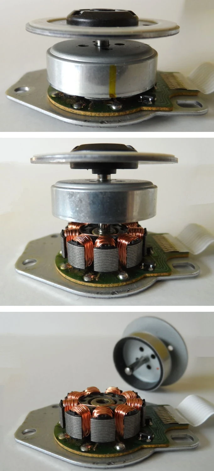
A frameless motor is supplied mainly as a wound stator and a permanent-magnet rotor without the bearings, shaft and finished housing of a conventional motor. The robot designer integrates those elements directly into the joint, gaining packaging freedom while accepting responsibility for the mechanical, thermal and electrical system.
This architecture can place torque close to the joint axis and remove duplicated housings. It does not make torque density automatic. Air gap, concentricity, winding selection, cooling, bearings, feedback, drive tuning and assembly repeatability determine whether catalog electromagnetic capability becomes useful joint output.
This guide connects the complete actuator structure to the robot reducer comparison. Datasheet values should be checked against the current winding and the final joint’s duty cycle.
Frameless describes the delivery form, not one motor physics
Kollmorgen’s frameless motor explanation describes rotor and stator components integrated into the machine structure. Many robot kits use brushless permanent-magnet topologies, but diameter, axial length, slots, poles, windings and magnets vary.
A kit may include a rotor hub or thermal sensor, yet the customer usually owns bearings, shaft, housing, alignment and feedback. Confirm exactly what is supplied and which performance assumptions depend on the customer’s heat sink and air gap.
Torque constant and speed constant follow the winding
The winding sets relationships among current, torque, voltage and speed. A high torque constant can reduce current for a given torque but also changes back EMF and available speed at the bus voltage. Phase resistance and inductance affect copper loss and current-loop behavior.
Compare continuous torque at the specified winding temperature and cooling condition. Peak torque is limited by current, magnets, drive and short-term heating. A winding chosen for one bus and speed may be unsuitable after the joint ratio or battery changes.
| Parameter | What it influences | Integration question | Validation |
|---|---|---|---|
| Torque constant | Torque per current | Required phase current | Calibrated torque test |
| Back EMF | Voltage needed at speed | Bus and speed margin | Speed-load sweep |
| Resistance | Copper loss | Winding temperature | Hot resistance test |
| Inductance | Current ripple and bandwidth | Drive switching and tuning | Current-loop response |
| Rotor inertia | Acceleration and control | Joint reflected dynamics | Identified system model |
The rotor and stator require a precise mechanical structure
The stator must be retained against reaction torque and conduct heat into the housing. The rotor must attach to a shaft or transmission input without shifting at speed or temperature. Adhesive, interference fits, sleeves and fasteners need defined assembly processes.
Bearings locate the rotor and carry external loads. Their arrangement sets runout and stiffness and can transmit assembly error into the air gap. Validate the complete tolerance stack rather than assigning motor alignment to one drawing dimension.

Air-gap control protects performance and hardware
Celera Motion’s motor air-gap guidance explains why the radial gap and concentricity matter. A smaller gap can improve electromagnetic coupling but leaves less tolerance for runout, thermal growth, bearing deflection and assembly variation.
Uneven gap can create unbalanced magnetic pull, torque ripple, vibration or contact. Check worst-case tolerance and structural deformation at operating speed and load. Inspect production units with defined gauges or metrology rather than relying on prototype assembly skill.
Thermal design sets continuous torque
Copper loss grows with current and winding resistance, while iron and mechanical losses rise with speed and magnetic behavior. Heat must cross the stator interface into the joint structure and then reach air, coolant or another sink. Interface material and contact pressure matter.
Temperature sensors observe only their location and can lag the hottest winding region. Build a thermal model, instrument prototypes and apply derating. Robot duty cycles should include simultaneous heating from the drive, reducer and neighboring components.
Feedback and commutation must share a trustworthy angle
Brushless drives need rotor electrical angle for commutation. Hall sensors, encoders or sensorless estimation can provide it depending on speed and safety needs. Mechanical encoder zero, electrical phase order and pole pairs must be configured correctly.
The robot encoder selection guide separates motor and output feedback. Incorrect offset can reduce torque, increase current and heat, or reverse behavior. Store calibration with the motor and joint identity.
The drive must match current, voltage and inductance
The inverter needs sufficient bus voltage, continuous and peak phase current, switching frequency, measurement quality and protection. Low-inductance motors can create current ripple or challenge a drive not designed for them. Cable length and placement affect EMI and sensing.
Tune the current loop with the installed motor and wiring. Validate over bus voltage, temperature and operating modes, including regeneration. Overcurrent, loss of feedback and phase faults need deterministic responses that integrate with robot safety control.
| Integration risk | Observable symptom | Likely source | Evidence |
|---|---|---|---|
| Air-gap error | Ripple, noise or rubbing | Runout or tolerance stack | Geometry and vibration sweep |
| Weak cooling | Torque derating or shutdown | Thermal interface | Duty-cycle temperature test |
| Commutation error | High current and low torque | Encoder offset or phase order | Torque-current calibration |
| Drive mismatch | Ripple or instability | Inductance and loop tuning | Current response logs |
| Assembly variation | Unit-to-unit performance spread | Process control | End-of-line statistics |
Transmission integration changes the motor load
A reducer multiplies output torque but reflects its friction and inertia to the motor. Direct and quasi-direct drive reduce transmission ratio but require more motor torque and current. The motor should be selected with the complete speed-torque trajectory, not one static point.
Consider rotor support, coupling, backlash, radial forces and generated heat. The shortest package is not automatically the lightest or stiffest after bearings, encoder, brake, reducer and housing are added.
Production requires repeatable assembly and calibration
Prototype motors can be aligned and tuned by experts. Production needs controlled adhesive, press fits, fastener torque, stator orientation, sensor placement, cleanliness and traceability. Magnets and windings also require handling and electrical safety procedures.
End-of-line tests should verify resistance, insulation, phase order, encoder alignment, no-load current, torque constant, vibration, temperature sensing and fault reporting. Link results to serial numbers so field drift can be compared with original evidence.
A motor test should reproduce the joint duty cycle
Map torque and speed through representative trajectories, dwell periods, reversals and ambient temperatures. Measure current, voltage, mechanical output, winding and housing temperatures, vibration and position. Include the intended drive and cooling path.
Test multiple assemblies and aged units. A suitable frameless motor is one whose integrated joint meets continuous output, control, efficiency, noise and lifetime goals with manufacturing margin. Electromagnetic catalog data is necessary but not sufficient.
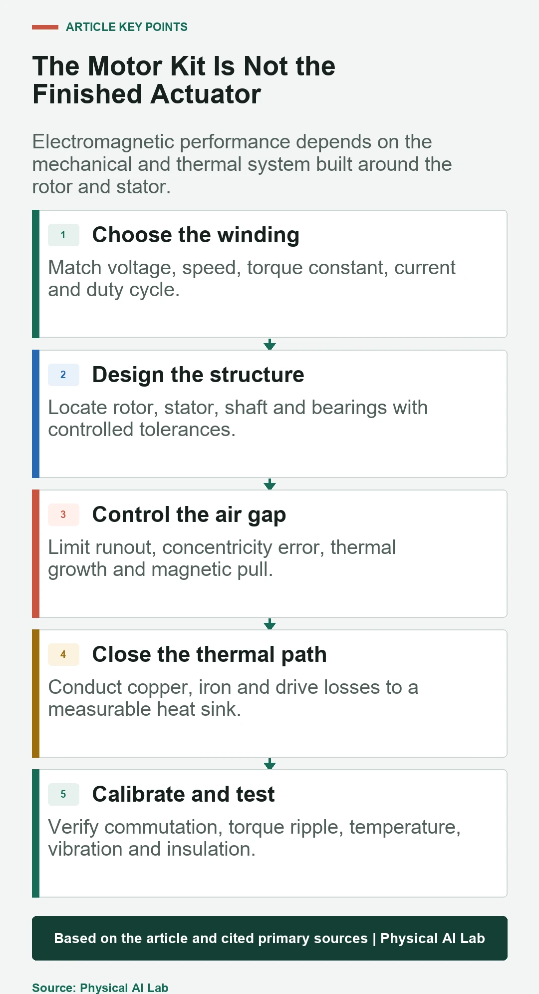
- Choose the winding from bus, speed and torque.
- Control air gap and bearing alignment.
- Validate the real thermal path.
- Calibrate feedback and commutation.
- Test production variation and duty-cycle life.
Frequently asked questions
What is a frameless motor?
It is commonly supplied as a rotor and wound stator without a finished motor housing and bearing system, so the machine or robot structure completes the motor.
Why do robots use frameless motors?
They allow compact custom packaging, direct thermal interfaces and integration with a reducer or joint structure. Those benefits require careful mechanical and thermal engineering.
Does a frameless motor need bearings?
Yes. The finished rotating system needs bearings or another support method. The robot designer typically supplies and aligns them.
What determines continuous frameless-motor torque?
Continuous torque depends on winding temperature, copper and iron loss, cooling, bus and drive limits, speed and the actual duty cycle.
How is a frameless motor commutated?
A drive uses rotor electrical angle from an encoder, Hall sensors or an estimation method. Phase order, pole count and electrical offset must be calibrated.
Motor Integration Note
Frameless motor ratings depend on winding, bus, drive, air gap, heat sink and temperature assumptions. Verify the current supplier documentation and test the assembled joint rather than extrapolating from a motor kit alone.