A robot joint actuator test must qualify the assembled motor, drive, transmission, bearings, sensors, brake, housing, lubricant and firmware under a defined duty cycle. A motor catalog point alone cannot predict joint output, accuracy, heat or life.
The test plan should connect application loads to calibrated measurements and explicit stop criteria. Peak torque, continuous torque, backlash, lost motion, friction, thermal steady state and wear are different properties and require different procedures.
Use this guide with the quasi-direct-drive actuator guide and joint thermal management guide. High-energy rigs require guarding, overspeed and overload protection, emergency stops and qualified test personnel.
The application duty cycle defines the test envelope
Translate robot tasks into output torque, speed, acceleration, direction changes, dwell, impacts, ambient temperature and pose. Include payload and reflected inertia across the reach envelope. Use measured or conservatively modeled distributions rather than one maximum number.
Define normal, peak, fault and recovery conditions. The same joint may need short high torque and lower continuous output. Acceptance should state duration, temperature limits, allowable drift and what happens after a protective event.

Freeze the specimen and rig configuration
Record motor, winding, transmission ratio, lubricant, bearings, seals, brake, sensors, inverter, bus voltage, firmware, control gains and housing. Small configuration changes can alter friction, heat and response enough to invalidate comparison.
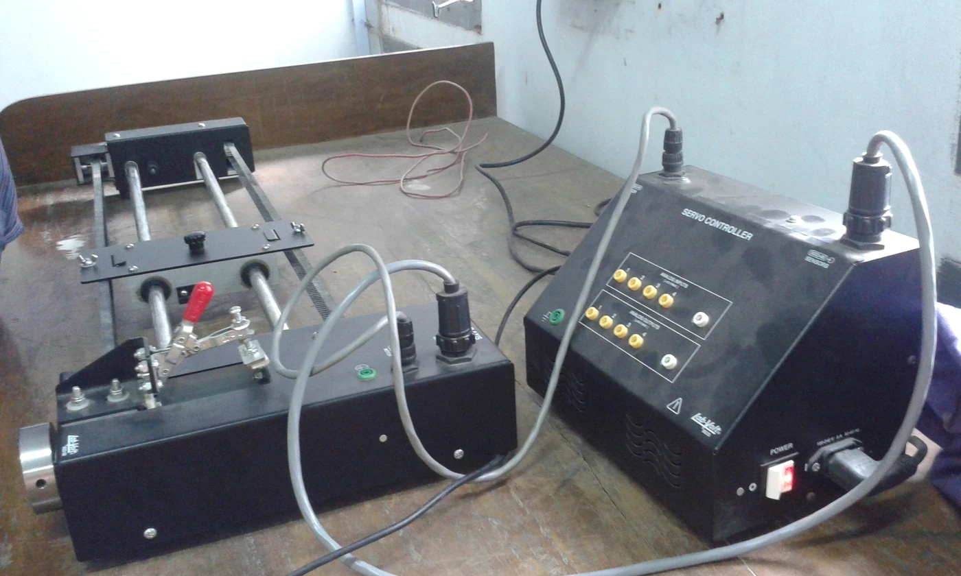
Document the load machine, couplings, alignment, fixtures, cooling and cable routing. A test rig adds compliance, friction and inertia. Measure its contribution or include it in uncertainty rather than attributing every result to the actuator.
Torque measurement depends on alignment and traceability
Use a calibrated reference transducer with suitable range, bandwidth and overload capacity. Open Dynamic Robot Initiative actuator hardware provides a useful public engineering reference, but every local rig still needs its own calibration and safety analysis.
Check zero, hysteresis, cross-axis load, temperature drift and mounting alignment. Compare commanded, estimated and reference torque. Report filtering and sampling because aggressive filtering can make ripple or transient error disappear.
| Test | Input control | Measured output | Key confounder |
|---|---|---|---|
| Static torque | Held current or load | Reference torque | Alignment and zero |
| Torque-speed map | Speed and load sweep | Torque, efficiency, temperature | Bus and cooling |
| Backlash | Reversal under low load | Angular dead band | Fixture compliance |
| Step response | Command transition | Rise, overshoot, settling | Filter and inertia |
| Thermal endurance | Duty cycle | Internal and surface temperature | Ambient and pose |
Peak and continuous torque require separate evidence
Peak torque is limited by current, magnetic saturation, transmission strength, traction and protective settings over a short duration. Continuous torque is limited mainly by losses, heat paths, ambient conditions and allowable component temperatures.
Report torque with duration, starting temperature, speed, cooling and repetition interval. A single peak value without these conditions is not a reusable rating. End the test at predefined temperature, vibration, noise or control limits.
A torque-speed map reveals the usable operating region
Sweep representative speed and load points in both directions. Record electrical input, mechanical output, efficiency, current, voltage, torque ripple and temperature. Hold long enough to separate transient behavior from a stable point.
Overlay the real duty-cycle distribution and controller limits. A joint can meet torque at low speed yet fail at higher back-EMF, voltage or thermal conditions. Interpolate cautiously and repeat boundary points.
Backlash, lost motion and stiffness are not interchangeable
Backlash is free movement between contacting elements under a defined condition. Lost motion can include elastic deformation, hysteresis, friction and control effects during reversal. Torsional stiffness relates load to angular deflection outside the free region.
Measure at defined loads, positions, directions and temperatures. Remove fixture compliance or report it. Repeat after run-in and life testing because wear, lubricant distribution and bearing preload change the result.
Friction and dynamic response expose low-speed control limits
Measure breakaway, Coulomb and speed-dependent friction in both directions. Gear and seal friction can vary with temperature, load and position. Low-speed stick-slip may dominate precision even when encoder resolution is high.
Use chirps, steps or trajectories that match the control objective. Report delay, bandwidth, overshoot and settling with the attached inertia. A fast unloaded joint may respond very differently with the robot link and payload.
| Acceptance area | Pass criterion example | Why average is insufficient | Retest trigger |
|---|---|---|---|
| Torque error | Bound across map | Local peaks matter | Calibration change |
| Backlash or lost motion | Worst position below limit | Wear is uneven | Life interval |
| Thermal | No component exceeds limit | Hotspot can be hidden | Cooling change |
| Response | Settling and overshoot bounded | One trace is selective | Firmware update |
| Life | Post-test drift within limit | Failure may be gradual | Noise or debris |
Thermal steady state belongs in performance testing
Place sensors where they can support estimates of winding, inverter, bearing and gearbox temperatures. Surface measurements alone may lag or miss internal hotspots. Record ambient, airflow, pose and adjacent heat sources.
Run the intended duty cycle until a defined steady-state criterion or protective limit. Then measure cooldown and recovery. Repeating short tests from a cold start can exaggerate continuous capability.
Life and overload tests need controlled acceleration
Life testing should reproduce relevant torque, speed, reversal, temperature and lubrication cycles. Simply multiplying load can introduce a different failure mode. Use engineering analysis to justify acceleration factors and preserve periodic baseline measurements.
For overload or impact tests, define fixture energy, protective settings, inspection intervals and immediate stop criteria. Track play, noise, vibration, particles, efficiency, insulation and sensor drift. Preserve failed parts for root-cause examination.
The report must make the result reproducible
Publish specimen configuration, rig drawings, calibration status, environment, commands, raw sampling, filters, uncertainty, stop events and excluded data. Link every chart to a test ID and software version.
Conclude against application-level acceptance criteria, not only supplier catalog values. Retain raw data and before-after measurements. A good report lets another engineer reproduce the point, understand uncertainty and decide whether the joint remains within a safe operating envelope.
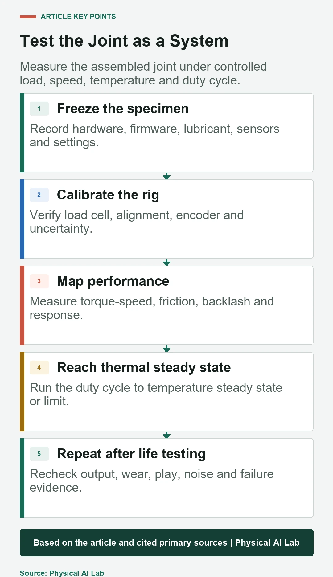
- Define the output-side duty cycle.
- Calibrate torque, angle, speed and temperature channels.
- Map static, dynamic and thermal behavior.
- Repeat key measurements after life exposure.
- Report uncertainty and all protective events.
Frequently asked questions
Can motor rated torque replace output-joint testing?
No. Transmission efficiency, friction, compliance, control and thermal paths change the assembled joint’s output.
Should backlash be measured only without load?
No. State the load, direction, position and temperature because lost motion and stiffness change with conditions.
How long is a continuous-torque test?
Long enough to reach the defined thermal steady-state criterion or limit under the intended duty cycle and environment.
Can life testing be accelerated by increasing load?
Only with justified acceleration models. Excess load can create failure modes that do not represent service.
What should determine pass or fail?
Application requirements with measurement uncertainty, worst-case conditions, safety margins and post-life drift should determine acceptance.
Test Safety and Uncertainty Note
Actuator test rigs can store hazardous electrical and mechanical energy. Use guarding, rated fixtures, independent overspeed and overload protection, emergency stops, calibrated instruments and qualified procedures; this guide is not a test certification.