A robot joint bearing keeps the output axis aligned while carrying radial force, axial force and overturning moment through a compact moving structure. The correct choice depends on the complete load path, stiffness target, mounting design and service conditions, not only a catalog load rating.
Crossed-roller, paired angular-contact and thin-section bearings solve different packaging and support problems. Preload can reduce clearance and increase rigidity, but it also raises friction, assembly sensitivity and heat. The housing, shaft, bolts and lubricant become part of the bearing system.
Use this guide with the joint actuator test guide and joint thermal guide. Final dimensions, fits, preload and life require current manufacturer data and qualified mechanical review.
Draw the load path before selecting a bearing
Resolve external forces at the end effector into radial, axial and moment loads at the joint across pose, payload, acceleration, impacts and cable forces. Include gravity and adjacent-link inertia rather than applying one nominal force at the bearing center.
Identify which rings rotate and where reactions enter the housing and shaft. A compact bearing cannot compensate for a flexible flange or a long unsupported offset. Define allowable output tilt, runout and friction as well as survival load.
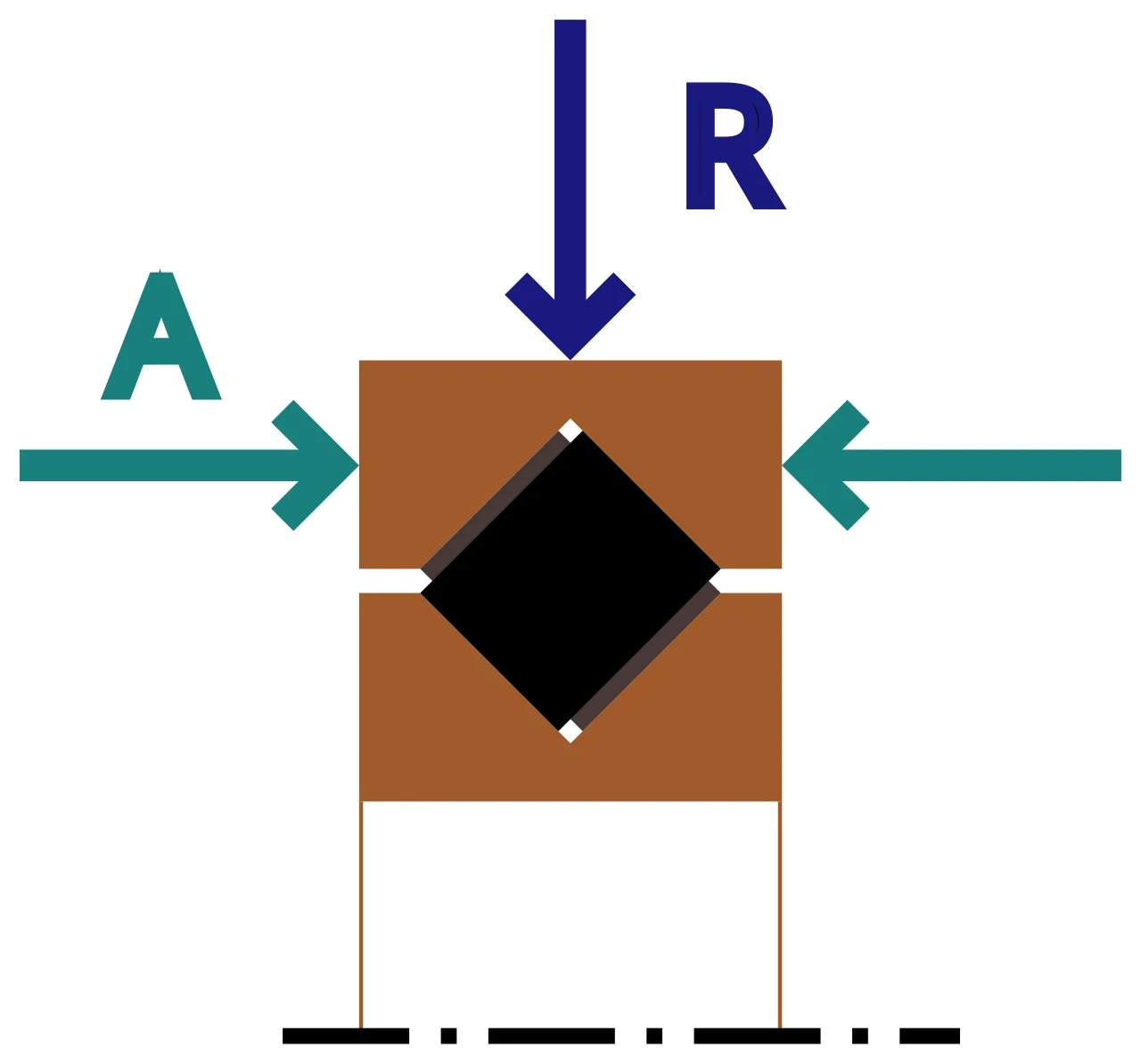

Crossed rollers support multiple load directions in one ring
THK describes crossed-roller rings with cylindrical rollers arranged perpendicular to adjacent rollers in a V groove. This lets one bearing carry radial, axial and moment loads in a compact envelope.
Line contact and alternating orientation can provide high rigidity, but performance depends on roller geometry, clearance, preload and ring support. Do not transfer one model’s marketing value to a different size, series or mounting condition.
| Bearing architecture | Main strength | Design sensitivity | Typical joint question |
|---|---|---|---|
| Crossed roller | Compact multi-direction support | Ring and flange deformation | Can one ring carry moment? |
| Paired angular contact | Configurable axial and moment support | Spacing and preload | Is a separated pair feasible? |
| Thin section | Large bore with small cross-section | Housing roundness and stiffness | Is routing space dominant? |
| Deep groove pair | Availability and low friction | Lower moment stiffness | Is load modest? |
| Custom integrated raceway | Packaging and mass | Manufacturing and service | Does volume justify integration? |
Paired angular-contact bearings use spacing and contact angle
Angular-contact bearings carry combined loads along a defined contact angle. Back-to-back or face-to-face pairs support axial load in both directions and create a virtual span that resists overturning moment.
Spacing can increase moment stiffness but consumes axial length and requires accurate shoulders and preload control. Define which ring is clamped, how thermal expansion changes preload and whether the pair can be serviced without disturbing encoder alignment.
Thin-section bearings trade cross-section for structural dependence
Thin-section bearings preserve a large central bore for cables, shafts or reducers while limiting radial package. Their small cross-section makes housing roundness, flange stiffness and fit particularly important.
Do not interpret thin as automatically weak or suitable. Compare the exact section, load direction, speed, oscillation and life. A light bearing in a distorted housing can have worse torque and life than a heavier bearing with controlled support.
Preload reduces clearance but consumes thermal and friction margin
Preload seats rolling elements and can improve rigidity and repeatability. Excess preload raises starting torque, heat, contact stress and sensitivity to fit or temperature. Interference that was not included in the design can create unplanned preload.
Measure rotational torque through assembly stages and over temperature. Use manufacturer clearance classes and fitting guidance. If stiffness requires high preload, first examine housing, flange and bolt compliance because structural improvement may deliver more margin.
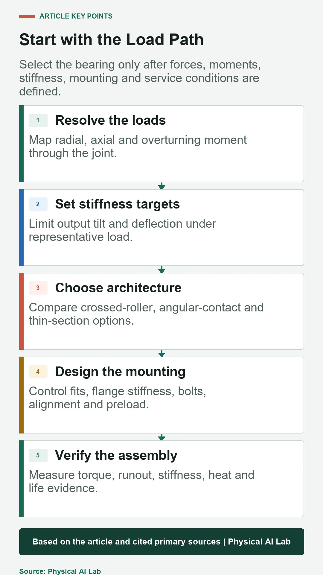
Housing, flange and bolts determine assembled rigidity
THK’s moment-rigidity guidance states that housing, presser flange and bolt deformation affect the result. Catalog curves for a separate ring are therefore not the joint’s final stiffness.
Model and measure the complete mounting stack. Control shoulder squareness, clamping pattern, surface finish and ring support. Tighten in a documented sequence and verify runout and torque before installing the reducer or encoder.
Life calculations must represent moments and oscillation
Convert the real load history into equivalent bearing loads using the applicable manufacturer method. Include moment, direction changes, shock factors, static safety and duty distribution rather than one average radial load.
Small oscillations can challenge lubrication because rolling elements may not redistribute lubricant as they do in full rotation. Review false brinelling, fretting and dwell conditions with the supplier. Accelerated life tests must preserve the relevant contact and lubrication regime.
| Verification | Measured quantity | Why it matters | Repeat condition |
|---|---|---|---|
| Runout | Radial and axial error | Encoder and output accuracy | After assembly |
| Rotational torque | Start and running torque | Preload and friction | Across temperature |
| Moment stiffness | Tilt under known load | Tool-point deflection | Representative pose |
| Thermal test | Bearing and housing temperature | Preload and lubrication | Duty-cycle steady state |
| Post-life inspection | Play, wear and debris | Degradation evidence | Defined cycle interval |
Lubrication and sealing change precision at low speed
Grease type, fill, distribution and viscosity influence friction, heat and life. Too much grease can raise torque; contamination or inadequate film can damage raceways. Seals add drag and can interact with pressure and temperature.
Specify lubricant, quantity, replenishment and compatibility with surrounding materials. Run in the assembly and record torque stabilization. Protect the bearing from machining debris, cable dust and cleaning fluids without creating excessive seal friction.
Replacement requires system-level requalification
After bearing replacement, verify fits, preload, runout, rotational torque, stiffness, thermal behavior and encoder calibration. A part with the same nominal dimensions may have different internal clearance or contact geometry.
Inspect the removed bearing and mounting surfaces for root cause. If failure came from flange distortion, overload or contamination, installing a new bearing without correcting the system will reproduce the damage.
Selection ends with an assembled-joint test
Choose architecture after comparing load capacity, stiffness, package, friction, thermal behavior, life, service and supplier controls. Confirm the mounting structure can maintain the selected clearance or preload across manufacturing tolerance and temperature.
Build a test that applies representative moment and duty cycle while measuring output deflection, torque, temperature and runout. The best bearing is the one whose complete assembly meets the robot requirement with credible manufacturing and service margin.
- Resolve radial, axial and moment loads by pose.
- Set output stiffness and runout limits.
- Include fits, preload and flange deformation.
- Review oscillation, lubricant and contamination.
- Requalify the assembled joint after changes.
Frequently asked questions
Is one crossed-roller bearing always better than two ball bearings?
No. Packaging, friction, stiffness, moment span, cost, mounting and service determine which architecture fits.
Are thin-section bearings always lower capacity?
Not categorically. Compare the exact series and load case, but their mounting structure often has greater influence.
Does more preload eliminate backlash?
Preload can reduce bearing clearance but cannot remove transmission backlash, housing deformation or control error, and excess preload raises heat.
Do small oscillations count in bearing life?
Yes. Oscillation changes contact and lubrication behavior and may require supplier-specific analysis beyond simple rotation assumptions.
What should be measured after bearing replacement?
Recheck runout, torque, stiffness, temperature, clearance or preload and any affected encoder or output calibration.
Bearing Application Note
Bearing ratings, fits, preload and life methods are product specific. Use the current manufacturer catalog, account for the complete mounting structure and validate the assembled joint under representative loads and temperature.