An RV reducer is a precision planocentric reducer commonly used in high-load robot joints. Its defining architecture combines an initial spur-gear reduction with eccentric crankshafts that drive cycloidal RV gears against a ring of pins.
Large reduction ratio, many simultaneous contacts and a robust output structure can provide high rigidity and overload resistance. Those strengths do not mean zero lost motion, constant efficiency or unlimited life. Bearings, pins, lubrication, housing and load history remain critical.
Compare this architecture with the harmonic-drive guide and use the joint actuator test guide for output-side verification. Product selection requires the manufacturer’s current rating method.
The first stage reduces speed through spur gears
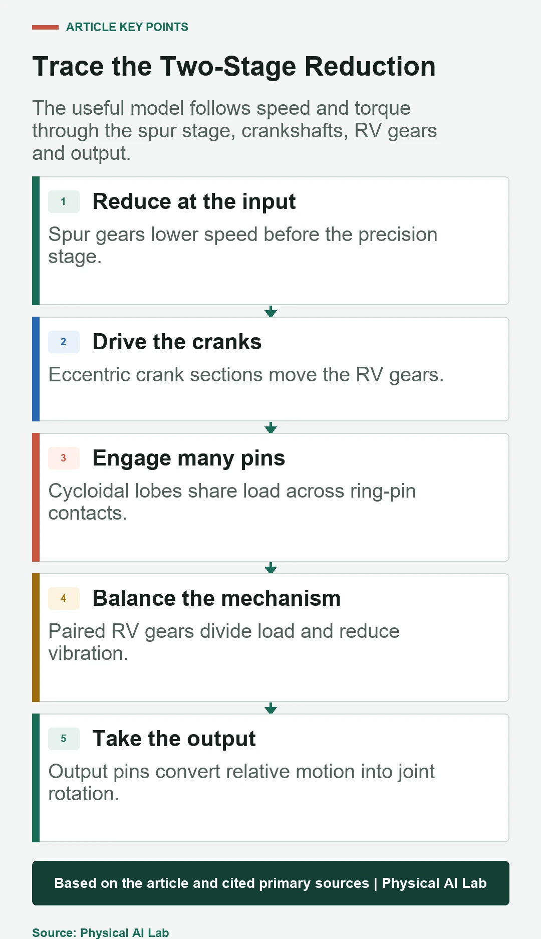
Nabtesco’s official operating-principle description begins with motor rotation transmitted from an input gear to spur gears on the crankshafts. This first stage provides part of the total ratio.
State input gear, spur gear and crankshaft tooth counts when analyzing ratio. Packaging variants can alter the arrangement. Do not treat a general cycloidal diagram as the complete commercial RV product.
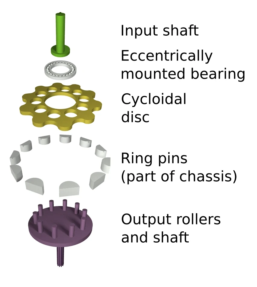

Eccentric crankshafts drive planocentric motion
Each crankshaft has eccentric sections supported by bearings. As the crankshafts rotate, the RV gears revolve eccentrically around the main axis rather than simply spinning like ordinary spur gears.
This motion requires accurate eccentricity, bearing support and synchronization among cranks. Errors become torque ripple, vibration, uneven contact or output variation. The surrounding case must maintain geometry under load.
A small tooth-count difference creates a large ratio
The cycloidal profile engages a ring of pins with a small difference between the number of lobes and pins. Each eccentric revolution produces a small relative rotation, creating high reduction in a compact diameter.
Calculate the complete ratio from both stages and the selected fixed and output members. Sign and direction depend on the reference frame. Verify vendor definitions before comparing ratios across products.
| Element | Motion role | Primary design effect | Failure sensitivity |
|---|---|---|---|
| Input and spur gears | First reduction | Ratio and packaging | Mesh error and noise |
| Crankshafts | Eccentric drive | Load transfer and phase | Bearing and eccentric error |
| RV gears | Cycloidal engagement | High ratio and contact sharing | Profile and elastic error |
| Ring pins | Reaction path | Load distribution | Wear and lubrication |
| Output pins or case | Relative-motion output | Joint torque and stiffness | Fit and bearing support |
Paired RV gears balance force and share load
Commercial RV mechanisms commonly use two RV gears phased on the eccentric sections. Nabtesco explains that the pair balances equal force. It can also distribute load and reduce vibration compared with one disc.
Load sharing is not automatically perfect. Manufacturing tolerance, elastic deformation and bearing condition affect each contact. Inspect wear patterns and torque ripple rather than assuming equal load from geometry alone.
Many engaged contacts support high rigidity
Multiple lobes and pins can carry load simultaneously, spreading contact compared with a single-tooth mesh. A robust crank and output structure also helps the reducer resist moment and shock.
Rigidity is an assembled property. Reducer internal compliance, output bearing, housing, fasteners and robot link all contribute. Compare torsional stiffness and moment capacity at the same mounting and load condition.
RV and harmonic reducers use different deformation mechanisms
An RV reducer uses eccentric planocentric motion and rolling or pin contacts through a rigid mechanism. A harmonic reducer elastically deforms a flexspline to create tooth-count difference. Both can provide high ratio and low nominal backlash.
RV units are often favored for high-load axes, while harmonic units can be attractive where low mass and compact coaxial packaging dominate. Selection must compare ratio, torque, moment, mass, lost motion, efficiency, shock, life and integration.
| Comparison | RV reducer | Harmonic reducer | Joint decision |
|---|---|---|---|
| Core motion | Eccentric cycloidal engagement | Flexspline deformation | Load and package |
| Load sharing | Many pins and lobes | Many gear teeth | Shock and duty |
| Compliance source | Contacts and structure | Flexspline plus structure | Control bandwidth |
| Typical strength | Rigidity and overload tolerance | Low mass and compact ratio | Axis role |
| Validation | Lost motion, heat and life | Flexspline fatigue and lost motion | Output-side test |
Low backlash does not mean zero lost motion
Catalog backlash may describe a narrow test region. Direction reversal also reveals elastic windup, bearing displacement, friction hysteresis and manufacturing variation. These effects combine as lost motion at the joint.
Measure output angle against reference torque across position, temperature and life. Include encoder placement: a motor-side encoder cannot observe all reducer deformation. Use output sensing if the application needs direct correction.
Efficiency and heat change across the operating map
Mesh, bearing, seal and lubricant losses depend on speed, torque, direction and temperature. Efficiency at one rated point does not predict low-speed friction or cyclic robot operation.
Map input power, output torque and temperature under the intended duty cycle. Confirm lubrication and mounting orientation. Thermal growth can change preload, lost motion and seal drag before a temperature protection threshold is reached.
Life follows the actual load history
Rated torque is not a complete lifetime description. Robot axes experience acceleration peaks, reversals, impacts, dwell and varying moment. Use the supplier’s equivalent-load and service-life method with the real distribution.
Inspect vibration, noise, lubricant condition, play and efficiency over life. An accelerated test must preserve contact stress and temperature regimes. Record shock events separately rather than averaging them into a smooth duty cycle.
Reducer selection ends at the robot joint
Check input inertia, motor speed, ratio, output torque, moment capacity, stiffness, lost motion, efficiency, heat, mass, bearing arrangement and service access together. The reducer can shift the motor’s operating region and controller tuning.
Validate the assembled joint with representative payload and trajectory. Measure output accuracy, reversal, thermal steady state, vibration and post-life change. A reducer is suitable when the complete joint meets the task, not when one catalog number is largest.
- Trace both reduction stages and reference members.
- Include crank and output bearing support.
- Measure lost motion under reversal and load.
- Map efficiency and temperature by duty cycle.
- Use product-specific life calculations and joint tests.
Frequently asked questions
Is an RV reducer the same as any cycloidal reducer?
RV is a specific precision architecture with a first reduction stage and product-specific crank, RV gear and output construction; cycloidal drive is broader.
Does an RV reducer have zero backlash?
No. It can have low nominal backlash, but elastic deformation, bearings, friction and wear create lost motion.
Is an RV reducer always stronger than a harmonic reducer?
No universal ranking applies. Compare the exact load, ratio, moment, mass, shock, life and package.
Why are two RV gears used?
The paired gears balance forces, share load and can reduce vibration when accurately manufactured and supported.
Will replacing only the reducer improve joint accuracy?
Not necessarily. Bearings, housing, encoder location, control, calibration and mounting can dominate the final error.
Reducer Configuration Note
RV reducer construction, ratings and life methods vary by product. Use current manufacturer drawings and calculations, then validate the complete joint under the intended torque, moment, speed, temperature and shock history.