A robot joint can need three different functions during a stop: controlled deceleration, removal of torque-producing energy and mechanical holding against gravity or an external load. Treating them as one function creates dangerous timing and diagnostic assumptions.
Safe Torque Off prevents the drive from producing motor torque but does not mechanically lock the axis. Safe Stop 1 initiates a controlled stop before transitioning to STO. A spring-applied holding brake can retain position, but only within its rated and validated conditions.
Use this guide with the Physical AI safety layers and joint actuator tests. Functional-safety design requires applicable standards, certified components, validated risk reduction and qualified professionals.
Stopping, holding and torque removal are different functions
Controlled stopping uses motor torque to reduce kinetic energy along a defined trajectory. Mechanical holding resists load after motion stops. STO removes the motor’s ability to generate torque. The required sequence depends on gravity, inertia, hazard and brake design.
Write a state diagram for normal stop, protective stop, emergency stop, power loss, communication loss and detected brake fault. Define safe state, maximum movement, timing, diagnostics and restart for each.

Spring-applied power-off brakes fail toward engagement
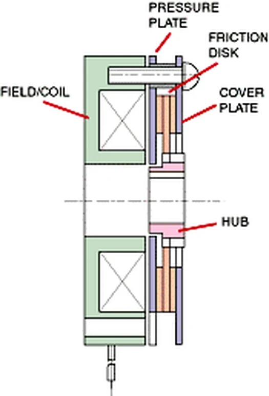
A common motor holding brake uses spring force to clamp friction surfaces when the coil is de-energized. Applying coil power releases it. This architecture can hold during power loss if mechanical, thermal and wear limits remain valid.
It is not automatically a dynamic emergency brake. Repeated high-energy stops can overheat or wear friction surfaces. Use product ratings for static holding, permitted emergency stops, engagement time, air gap and life.
| Function | What it does | What it does not prove | Required evidence |
|---|---|---|---|
| Controlled stop | Reduces speed with drive torque | Safe torque removal | Monitored stop behavior |
| STO | Prevents torque production | Mechanical holding | Drive safety validation |
| SS1 | Stops then transitions to STO | Gravity retention alone | Timing or ramp monitoring |
| Holding brake | Resists axis load | Full safety performance | Torque and wear test |
| Brake feedback | Reports switch or command state | Actual holding force | Periodic functional test |
STO does not hold a gravity-loaded axis
Siemens’ 2025 Safety Integrated manual includes STO and SS1 functions, while its application guidance warns that hanging or gravity axes may require a service or holding brake.
After STO, an unrestrained axis can coast or fall under load. Evaluate gravity, counterbalance, friction, external force and single faults. Do not rely on gearbox friction as a safety-rated holding function.
SS1 controls deceleration before torque is removed
Safe Stop 1 initiates braking and then triggers STO after a defined delay or monitored stopping condition, depending on implementation. Motor torque remains available during the deceleration portion.
The interval must allow the axis to reach the intended state and any holding brake to engage before torque removal. Validate worst-case speed, load, temperature, bus behavior and brake closing time. A nominal ramp is not enough.
Brake timing must account for load transfer
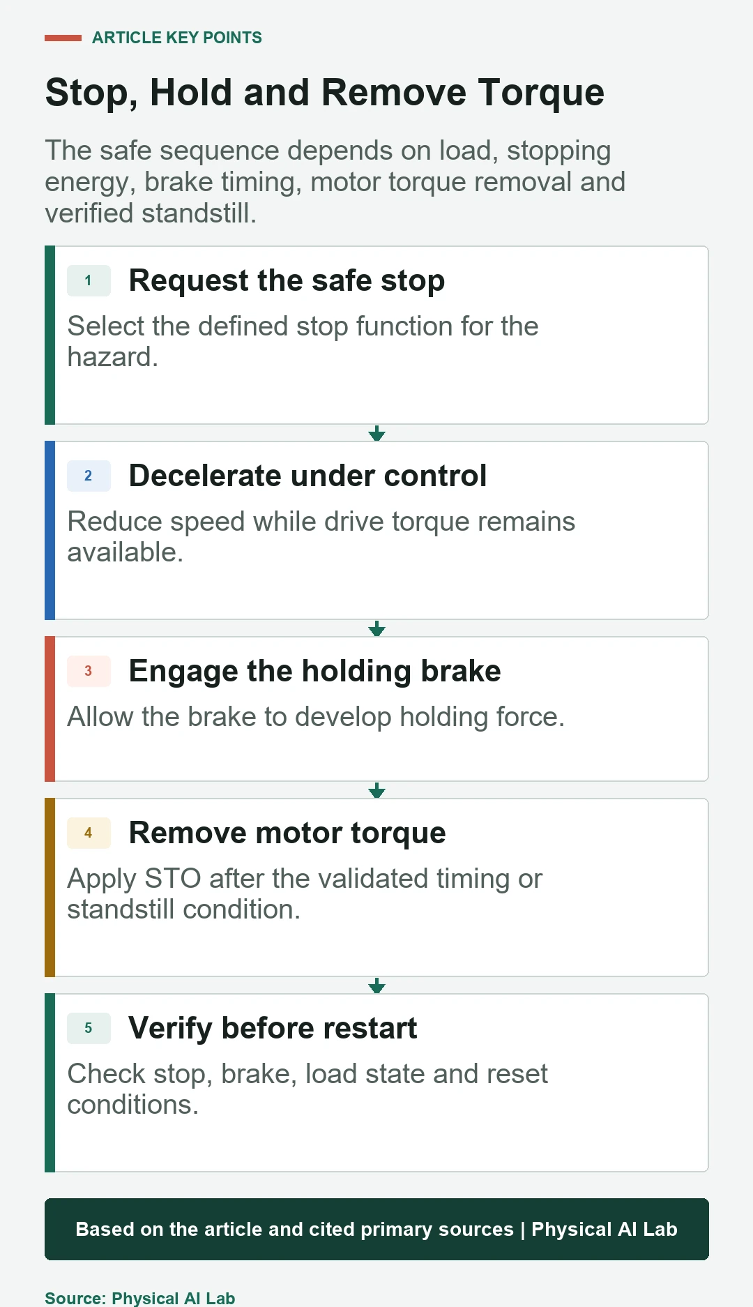
Engaging a brake while the axis still moves creates friction energy and shock. Removing motor torque before the brake develops holding force can allow a drop. The controller must coordinate deceleration, standstill, brake command, engagement and STO.
Measure actual movement and torque through the sequence. Include command latency, coil release or engagement time, mechanical air-gap variation and voltage tolerance. Use independent monitoring where required by the risk reduction.
Holding torque needs margin for temperature and wear
Brake holding capacity changes with friction material, temperature, contamination, wear, air gap and orientation. Static catalog torque should not be equated with verified joint holding across life.
Calculate the output-side gravity and external torque, including transmission ratio and efficiency in the unfavorable direction. Apply required safety factors and test at boundary temperatures and wear states. Inspect for oil or grease migration.
| Test scenario | Initial condition | Pass evidence | Hidden risk |
|---|---|---|---|
| Power loss | Worst gravity pose | Bounded movement and hold | Coil and drive timing |
| SS1 stop | Maximum permitted speed | Stop before STO boundary | Ramp or monitoring fault |
| Brake wear | Defined life state | Holding torque with margin | Air-gap growth |
| Sensor fault | Feedback stuck or inconsistent | Detected safe reaction | Command-state confusion |
| Restart | Unknown or recovered load state | Verified release and control | Unexpected jump |
Brake feedback does not measure holding force
A microswitch or internal status may indicate command or mechanical position. It does not prove friction torque, surface condition or full engagement under load. Interpret exactly what the sensor measures.
Combine status monitoring with periodic brake tests where required. A safe brake test can apply controlled torque and verify that movement remains within a limit. Define detection thresholds and action after failure.
Power and communication failures need separate tests
Mains loss, control-power loss, fieldbus interruption and safety-network fault can produce different sequences. Stored bus energy may support a stop, or torque may disappear immediately. Brake supply and release circuits have their own behavior.
Test each fault at representative speed, load and pose. Record movement, stop time, brake state and restart. Verify that loss of diagnostics does not silently permit motion or a premature reset.
A holding brake does not eliminate collision risk
A brake can prevent or limit gravity motion after stopping, but it does not make the earlier trajectory safe. Protective distances, speed limits, force control, guarding and independent stop functions still address other hazards.
Brake engagement can itself move or shock a load. Consider suspended tools, pinch points and people below an axis. Mechanical restraint may be needed for maintenance even when a holding brake is present.
Restart requires verified state and controlled release
After a stop or power loss, confirm axis position, brake status, load support, controller state and the cause of the stop. Releasing the brake before torque control is established can cause a drop or jump.
Design a documented sequence that establishes motor torque, releases the brake, verifies release and returns to motion only after authorization. Test sensor disagreement and failed release. Every restart path should lead from a known safe state.
- Separate deceleration, STO and mechanical holding.
- Size and test the brake across wear and temperature.
- Validate engagement timing at worst load and speed.
- Inject power, communication and feedback faults.
- Require known state before brake release and restart.
Frequently asked questions
Does STO immediately lock a robot joint?
No. STO prevents motor torque production; the axis may coast or move under gravity unless another mechanism holds it.
Can a holding brake perform every emergency stop?
Usually not. Many motor brakes are intended primarily for holding and have limited dynamic-stop energy and life.
Is brake torque above gravity torque enough?
Not by itself. Include safety margin, temperature, wear, contamination, transmission behavior and validated stop timing.
Does a brake feedback switch prove holding force?
No. It reports a defined state or position, not actual friction torque. Periodic functional testing may be required.
Can the robot restart immediately after power returns?
Restart should wait until position, load, brake, control and fault state are verified and brake release is safely coordinated.
Functional Safety Boundary Note
This article explains concepts and does not design or certify a safety function. Apply the current machinery, drive and robot safety standards for the jurisdiction and product, use certified components where required, and validate achieved risk reduction.