A robot tactile sensor measures what happens after contact: where the object touches, how pressure is distributed, whether shear is building and whether slip has begun. It complements cameras, encoders and wrist force-torque sensors by resolving local interaction at the finger or skin surface.
Tactile hardware can use resistive, capacitive, piezoelectric, magnetic, optical or fluidic principles. Each has a different balance of spatial resolution, bandwidth, hysteresis, drift, durability and packaging. The useful system also needs calibration, time alignment, protective skins and closed-loop behavior.
Use this guide with the robot gripper selection guide and force-torque sensor guide. Sensor outputs are not universal force truth; validate them with the installed finger, cover, temperature and expected contact set.
Tactile sensing resolves local contact after touch
Vision estimates object pose before and during approach but can lose the contact region to occlusion. A wrist force-torque sensor measures the aggregate wrench transmitted through the tool. A tactile array adds spatial evidence from individual fingertips or skin patches.
Define the decisions the sensor must support: first contact, contact centroid, pressure distribution, normal force, shear, slip, texture or material classification. Required range, resolution and sample rate differ for each task.

Pressure arrays turn a surface into many taxels
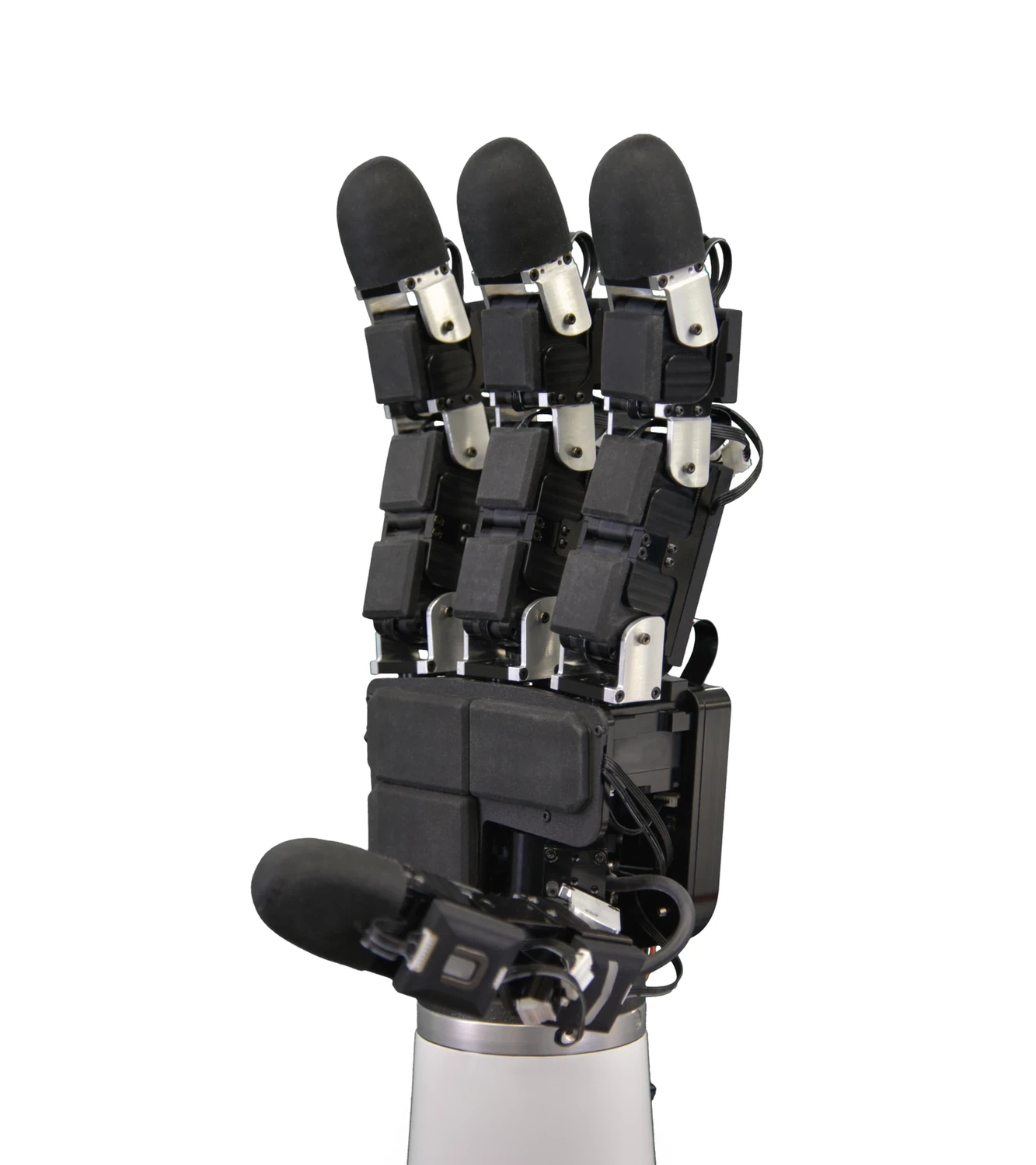
A tactile array contains sensing cells commonly called taxels. Their geometry and spacing determine the observable contact patch. Mechanical layers above the array spread load, protect the device and change spatial response, so nominal pitch is not the same as effective resolution.
Calibrate the assembled stack rather than the bare element when possible. Record dead regions, cross-talk and edge behavior. A sum of taxel readings may estimate normal load, but that estimate depends on contact geometry and the calibration range.
| Sensor family | Measured effect | Main strength | Design concern |
|---|---|---|---|
| Piezoresistive | Resistance change | Simple pressure arrays | Hysteresis and drift |
| Capacitive | Gap or dielectric change | Sensitivity and arrays | Shielding and moisture |
| Piezoelectric | Dynamic charge | Fast vibration and impacts | Weak static response |
| Magnetic elastomer | Field change | Three-axis local force | Magnet and temperature variation |
| Vision based | Deformed optical skin | Rich contact geometry | Bulk, lighting and skin wear |
Vision-based tactile sensors observe surface deformation
Meta’s DIGIT and tactile ecosystem overview describes optical sensing that images a compliant surface and supports learned functions such as touch, slip and pose estimation. The camera sees deformation hidden from an external view.
Optical designs provide dense information but require stable lighting, optics, markers and compliant skin. Contamination, scratches and replacement skins can shift the data distribution. Calibrate and version the physical surface with the model.
Normal force, shear and contact patch are different outputs
Normal pressure acts into the surface, while shear acts tangentially and often precedes slip. Contact centroid and patch shape help determine whether an object sits on the intended finger area. A sensor that reports one scalar force may not distinguish these conditions.
Apply known loads and directions across the expected contact positions. Report component cross-talk and uncertainty rather than only one best-fit curve. For curved fingertips, transform local measurements into a consistent finger or object frame.
Slip appears as a temporal event, not only lower pressure
NIST’s tactile slip-detector study evaluated sensing technologies through sampling rate, data-window size, material, slip speed and sensor variability. Incipient slip can create vibration or local shear change before gross loss of contact.
Use temporal or spectral features appropriate to the sensor bandwidth. Test diverse materials, surface finishes, velocities and normal forces. A threshold tuned on one object may confuse intentional rolling contact, impact or motor vibration with slip.
Calibration must cover force, position, temperature and replacement
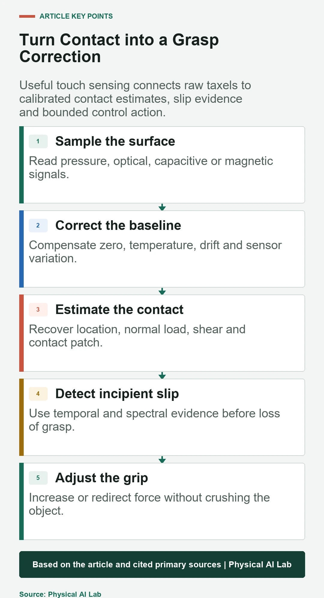
Zero each sensing cell and characterize gain, nonlinearity, hysteresis, repeatability and saturation. Temperature and long-term drift can change baselines. Replaceable skins, adhesives and mechanical preload also alter the response.
Keep calibration identifiers with logged data. Use reference fixtures that apply known location and force. Recheck after maintenance or a detected drift event. A model trained on one sensor serial number should be evaluated on other units before fleet deployment.
| Calibration check | Input varied | Metric | Recheck trigger |
|---|---|---|---|
| Zero and drift | Time and temperature | Baseline distribution | Warm-up or ambient change |
| Normal load | Force and position | Gain and nonlinearity | Skin replacement |
| Shear load | Direction and magnitude | Cross-axis error | Finger repair |
| Dynamic response | Frequency and impact | Bandwidth and latency | Firmware change |
| Unit variation | Sensor serial number | Transfer error | Fleet expansion |
Grasp control should add only the force that is needed
A tactile controller can increase grip when slip evidence rises and reduce force when contact is stable. The aim is not maximum pressure. Excess force can deform products, saturate sensors, increase friction uncertainty and shorten gripper life.
Coordinate tactile feedback with actuator current, finger position and wrist wrench. Bound the correction rate and total force. Test sensor dropout and false slip so the controller does not clamp indefinitely or release an object without a safe fallback.
Tactile data needs synchronized context
Store raw or minimally processed sensor data with finger pose, joint state, commanded force, object identity, action phase and timestamps. Contact labels without the robot state are difficult to reuse because the same pattern can mean different events.
Version sensor geometry, calibration, skin material, firmware and preprocessing. Preserve failed grasps and recovery attempts. Balanced datasets should include no-contact, light contact, stable grasp, rolling, slip and overload examples across objects and sensor units.
Wear and contamination are part of the sensing model
Fingertip skins repeatedly rub, compress and collect dust or oils. Optical surfaces scratch, elastomers change stiffness and taxel wiring can fatigue. Protective covers improve serviceability but may reduce sensitivity or blur contact location.
Define inspection, cleaning and replacement intervals from measured drift and damage. Add health checks for stuck cells, noise, saturation and baseline shift. Recalibrate or retrain after changes that affect the mechanical interface.
Tactile sensing complements rather than replaces vision
Vision is efficient for scene and object geometry before contact; touch is strongest at the occluded interface after contact. Combining them supports approach planning, contact confirmation, pose correction and slip recovery.
Evaluate the incremental benefit. Compare success rate, damage, cycle time and recovery with vision only, force sensing and tactile fusion. Select tactile hardware only when the improvement survives object variation, wear and operational maintenance.
- Name the contact decision before choosing a sensor.
- Calibrate the installed fingertip across force and position.
- Measure latency and slip performance on varied materials.
- Synchronize tactile data with action and robot state.
- Plan for wear, replacement and sensor-to-sensor variation.
Frequently asked questions
How is a tactile sensor different from a wrist force-torque sensor?
A tactile sensor resolves local contact across a finger or skin surface, while a wrist sensor measures the aggregate wrench through the tool.
Can cameras replace tactile sensors?
Cameras help before contact, but contact areas can be occluded and local shear or incipient slip may not be visible.
Can touch identify material?
Tactile signals can support classification of texture, compliance and other properties, but models need representative contacts, sensors and calibration.
Is slip detected only when pressure falls?
No. Vibration, shear redistribution and local motion can provide earlier evidence than a large decrease in total normal load.
Is one calibration permanent?
No. Temperature, drift, wear, skin replacement and unit variation can require recalibration or model validation.
Tactile Measurement Note
Tactile measurements depend on the complete fingertip stack, contact geometry, calibration and operating environment. Validate force and slip performance across expected objects, sensor units, wear states and temperatures before using tactile feedback in production.