Collaborative robot safety starts with a specific human-robot task, not with a product category. A robot marketed as collaborative can still create unacceptable risk when a sharp tool, heavy workpiece, trapping point, unexpected restart or high-energy process is added. The integrator must assess and validate the complete application.
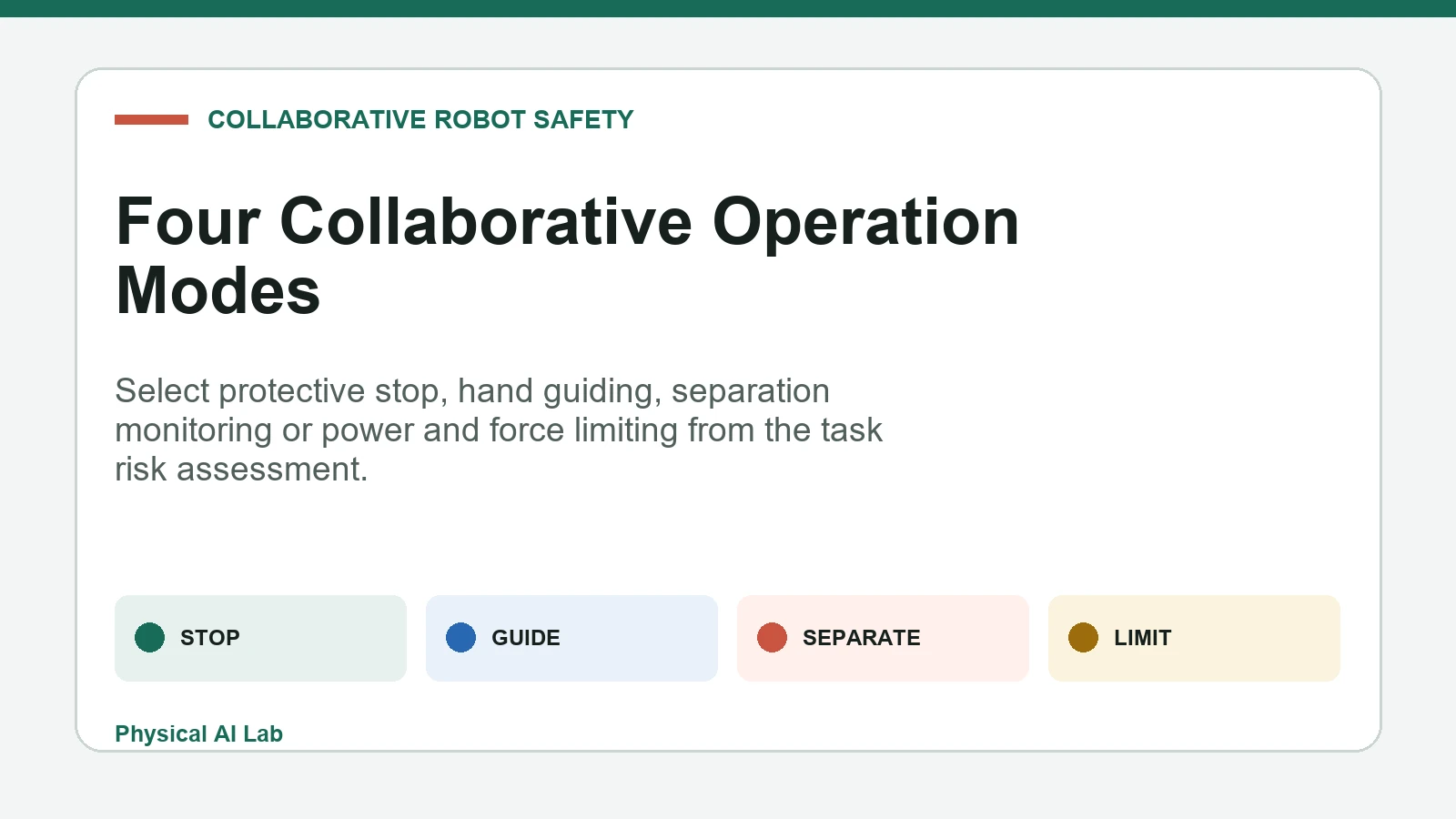
Industrial standards describe four collaborative operating methods: safety-rated monitored stop, hand guiding, speed and separation monitoring, and power and force limiting. They answer different questions about when people may enter, whether robot motion continues, whether contact is intended and how harmful energy is controlled.
Use this guide with the robot functional-safety guide and collision-detection guide. Neither low speed nor a sensitive arm removes the need to identify hazards, design safeguards and measure the final cell.
Treat collaboration as an application property
Collaboration describes an operating situation in which a person and an industrial robot share a safeguarded space or work on a related task. It does not mean unrestricted proximity. Different phases such as production, loading, teaching, jam clearing and maintenance may need different safeguards and access rules.
Start with people, motion, payload, end effector, workpiece, fixtures and the surrounding machine. Include foreseeable misuse: reaching around a sensor, entering from an unmonitored side, bypassing a fixture or resetting before the person has left. The risk assessment determines whether collaborative operation is appropriate at all.

Match the four methods to motion and contact
A safety-rated monitored stop prevents robot motion while a person is in the collaborative workspace. Hand guiding permits an authorized person to command motion through a suitable device. Separation monitoring changes robot behavior as distance closes. Power and force limiting controls the consequences of permitted contact.
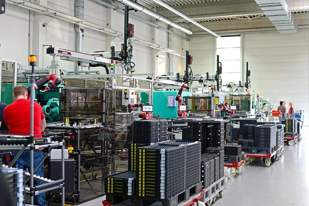
A cell can use more than one method across its operating sequence. For example, separation monitoring may slow approach, a monitored stop may protect loading, and power and force limits may address a residual transient contact. Every transition needs defined conditions and a safe response when evidence becomes invalid.
| Method | Robot motion near person | Contact assumption | Primary evidence |
|---|---|---|---|
| Safety-rated monitored stop | Stopped | Not required | Stop state and prevention of restart |
| Hand guiding | Operator-commanded | Guiding interaction | Enabling device, speed and control authority |
| Speed and separation monitoring | Conditional | Avoided by distance | Detection field and stopping distance |
| Power and force limiting | May continue | Possible or intended | Contact force, pressure and geometry |
| Combined application | Phase dependent | Scenario dependent | Validated transition logic |
Use a safety-rated monitored stop for shared access
In this mode, the robot reaches and maintains a monitored stop before or as the person enters the collaborative workspace, according to the protective design. Drive power may remain available, but hazardous motion must not resume merely because a sensor clears or communication returns.
Measure stop initiation, final standstill and prevention of unexpected restart. Check gravity, brake behavior, external axes, suspended loads and stored pneumatic or spring energy. A stationary robot can still present crushing, release or falling hazards if the application is not mechanically controlled.
Hand guiding needs explicit control authority
Hand guiding is not simply pushing a backdrivable arm. The application needs an intentional guiding device or interface, enabling conditions, bounded speed and a clear relationship between operator input and robot motion. Releasing the enabling function or detecting a fault should lead to the specified safe response.
Evaluate reach, visibility, pinch points and the person’s body position throughout the guided path. The operator may concentrate on the tool and fail to see another link approaching a fixture. Validate direction, gain, deadband, release behavior and transfer of authority back to automatic operation.
Speed and separation monitoring is a timing problem
Separation monitoring requires a protective sensing system, reliable position or speed information and a stopping model. The distance budget includes sensing delay, logic delay, robot reaction, braking distance, intrusion speed, uncertainty and any required supplemental margin. A field drawn on a layout is not evidence by itself.
Test the fastest credible approach, the robot’s least favorable pose and speed, sensor blind zones, reflective clothing, carried objects and simultaneous entrants. If tracking is lost, data is stale or the protective field becomes invalid, the system must transition to the defined protective state.
| Validation item | Measure | Adverse condition | Acceptance question |
|---|---|---|---|
| Person detection | Coverage and response time | Blind angle or occlusion | Is every access path protected? |
| Robot state | Speed and position error | Network or encoder fault | Is the distance calculation conservative? |
| Stop performance | Reaction and stopping distance | Worst payload and pose | Does motion stop before the boundary? |
| Contact result | Force and pressure | Tool edge or trapping | Are limits met for the scenario? |
| Restart | Reset and re-entry logic | Person remains inside | Can motion resume unexpectedly? |
Power and force limiting controls contact consequences
Power and force limiting relies on robot mechanics, sensing, control limits and application geometry to keep contact consequences within the risk-reduction design. Transient impacts and quasi-static trapping are different. A compliant arm cannot make a sharp tool, hot process or crushing fixture harmless.
Test representative body locations, approach directions, speeds, payloads and robot configurations using an appropriate measurement device and procedure. The ISO/TS 15066 collaborative-robot specification supplies important biomechanical context, but local regulation, the current application standard and competent safety engineering govern acceptance.
Tooling and workpieces change the risk
End effectors determine contact area, edges, heat, stored energy and whether a body part can be trapped. A soft robot cover does not control a drill, blade, gripper finger or workpiece corner. Include hoses, cables, quick changers and dropped-object paths in the hazard analysis.
Payload changes stopping distance, impact energy and joint limits. Fixtures create fixed surfaces against which a person can be pinned. Validate every approved tool and payload combination, and use configuration control so an unapproved attachment cannot silently inherit the original safety claim.
Measure the final cell instead of trusting labels
Manufacturer safety functions provide building blocks and limits, not certification of the integrated task. Record the robot model, safety software, configuration checksum, tool, payload, floor mounting, sensor positions and measurement equipment. Test the installed geometry after commissioning.
The current ISO 10218-2:2025 covers integration of industrial robot applications and cells, while ISO 10218-1:2025 addresses the industrial robot. Apply the edition and regional requirements relevant to the project rather than relying on an old generic checklist.
Restart and mode changes are separate hazards
A protective stop does not define who may reset it, where reset occurs or what must be visible. Reset should acknowledge a condition; it should not automatically initiate hazardous motion. Check that a person inside the workspace cannot be hidden from the reset location or bypass the intended sequence.
Test power restoration, controller restart, network reconnection, tool change, manual-to-automatic transfer and recovery from a protective fault. Log the active operating mode and safety state. Ambiguous indicators or stale HMI status can cause a correct safety function to be used incorrectly.
Connect functional safety to physical validation
Performance Level or Safety Integrity Level analysis addresses the integrity of safety-related control functions. It does not prove that the protective distance is sufficient or that a measured contact is acceptable. Functional integrity and application geometry are complementary evidence layers.
Trace each hazard to a safety function, required integrity, sensors, logic, actuators, diagnostic coverage and physical acceptance test. NIST’s task-based human-robot collaboration work reinforces the need to characterize the actual manufacturing task rather than a robot in isolation.
Revalidate every safety-relevant change
Changes to payload, tool, speed, trajectory, layout, floor condition, sensor mounting, firmware or safety parameters can alter the validated envelope. Classify changes before deployment and state which risk-assessment and test artifacts must be repeated. Keep previous configurations recoverable for investigation.
Schedule periodic inspection for protective sensors, brakes, covers, cables, fasteners and reset devices. Trend stopping measurements rather than recording one commissioning value forever. A drifting brake or moved sensor can consume margin while the software still reports a healthy status.
Build an auditable acceptance package
The handover package should include the risk assessment, safety-function specification, calculations, configuration records, test methods, calibrated measurements, residual risks, training requirements and change-control process. State exactly which collaborative method applies in each operating phase.
Use these acceptance gates before production release and after material changes. Evidence should let another qualified reviewer reproduce the decision rather than infer it from a vendor name or a successful demonstration.
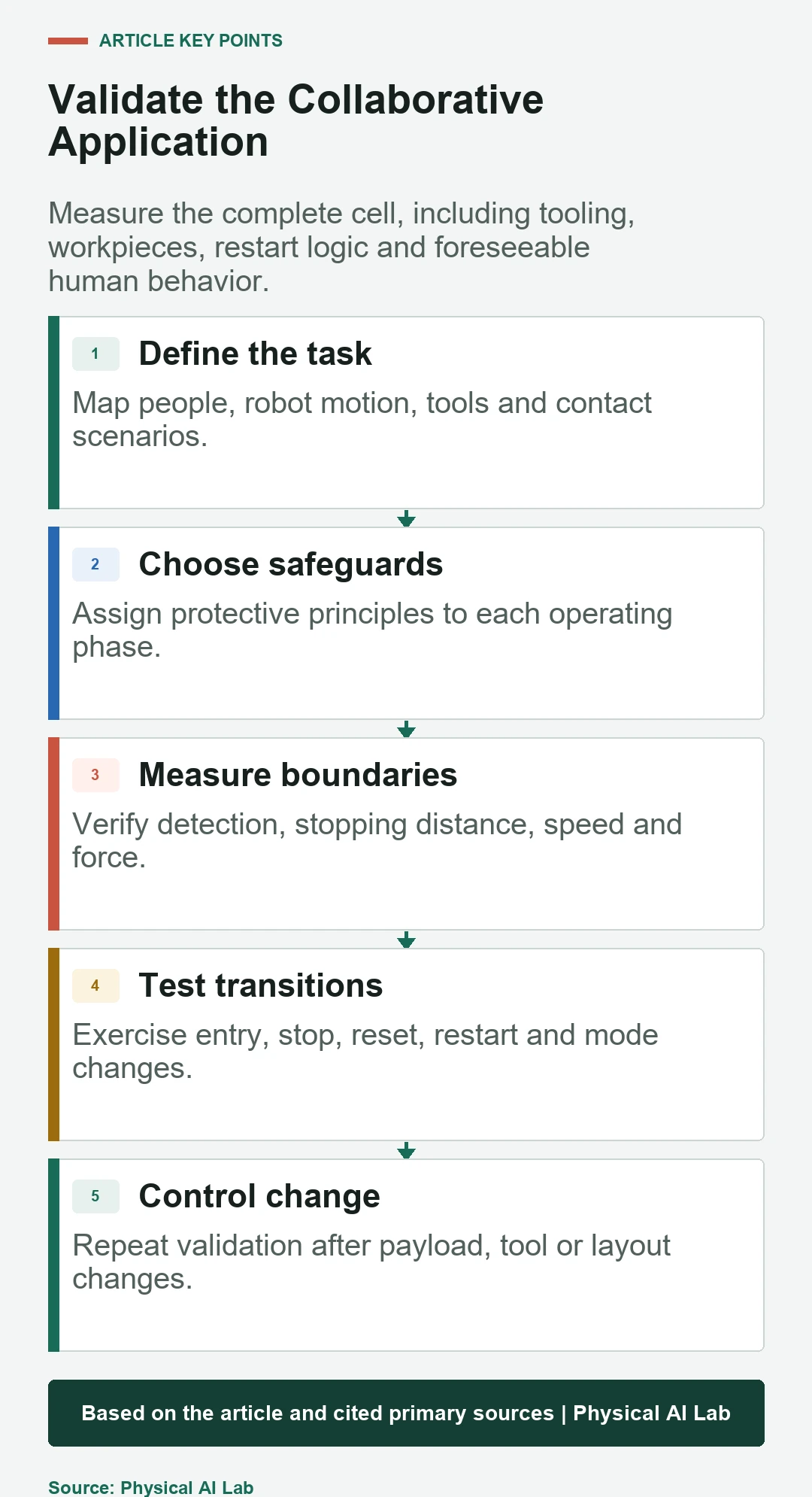
- Map every human access and contact scenario.
- Assign one or more protective methods to each phase.
- Measure detection, stop, distance and contact behavior.
- Verify reset, restart and mode transitions.
- Control tools, payloads, software and layout changes.
Frequently asked questions
Does a collaborative robot eliminate the safety fence?
No. A risk assessment may still require guards, interlocks or restricted zones for some phases, tools or hazards.
Can low speed replace power and force testing?
No. Speed influences contact energy, but geometry, payload, trapping and control response also determine the result.
Can an ordinary camera provide separation monitoring?
Only a protective sensing solution and architecture validated for the required safety function should be used. Image quality alone is not sufficient.
Is hand guiding the same as physically pushing the arm?
No. Hand guiding requires defined control authority, enabling conditions, bounded motion and safe behavior when the guiding input is released or fails.
What should be retested after changing a cobot cell?
Reassess affected hazards and repeat relevant stop, separation, contact, restart and functional-safety tests for the changed configuration.
Collaborative Application Safety Boundary
This guide explains engineering concepts and does not certify an application. Apply current standards, local law, manufacturer instructions and a competent machinery-safety assessment to the installed cell.