URDF and SDFormat are XML robot-description formats with overlapping elements but different scopes. URDF is central to many ROS tools for one robot’s links and joints. SDFormat can describe models, lights, sensors, plugins, physics and complete simulation worlds.
Neither format guarantees physical fidelity. Visual, collision and inertial geometry can disagree; frame semantics can change through conversion; sensor rate and noise can be unrealistic. Select a source-of-truth strategy and inspect the generated model consumed by each tool.
Use this guide with the TF2 coordinate-frame guide and virtual commissioning guide. Validate structure, frames, physics and sensors separately.
Choose by consumer and validation scope
List every consumer: robot_state_publisher, kinematics, planning, visualization, control, simulator, world editor and asset pipeline. Record which format and version each accepts. One universal file can accumulate tool-specific extensions that no single consumer interprets consistently.
Define which behaviors must match the physical robot. Kinematic planning may need joints and collision geometry; controller testing needs transmissions and interfaces; simulation may need inertia, friction, contacts, sensor noise and world conditions.

URDF centers one kinematic tree
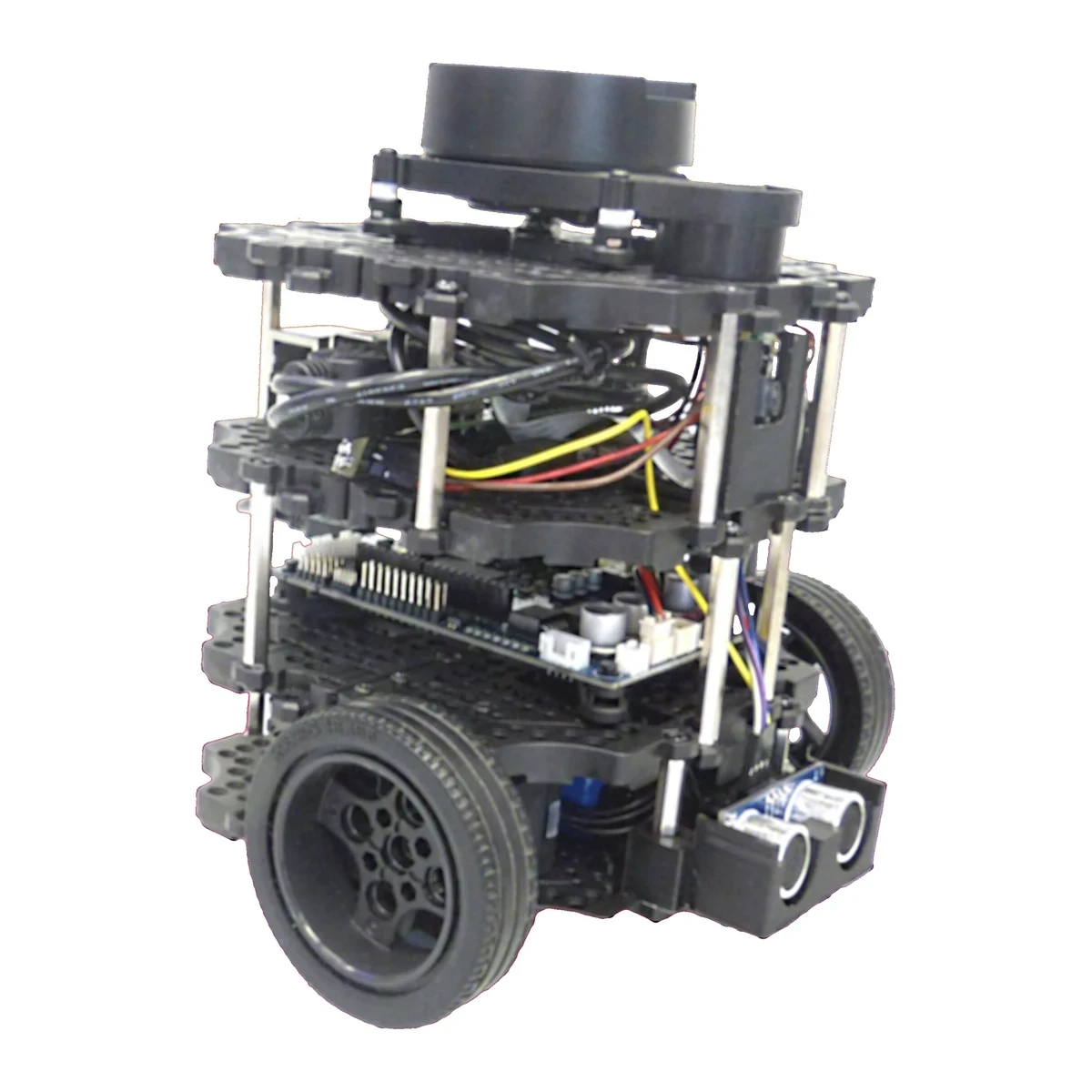
URDF describes links connected by joints and commonly stores visual, collision and inertial properties. Its tree structure aligns with robot_state_publisher and many ROS tools. Xacro adds reusable generation but is a preprocessing language, not a runtime robot model.
The ROS 2 URDF tutorials explain the ecosystem. Archive rendered URDF because macros, arguments and package paths determine the file actually consumed.
| Need | URDF strength | SDFormat strength | Validation |
|---|---|---|---|
| ROS kinematic tree | Broad tool support | Conversion may be needed | Joint and frame test |
| Simulation world | Extensions required | Native world structure | Spawn and environment test |
| Multiple models | External launch logic | World and nested models | Identity and pose test |
| Sensors and physics | Tool-specific tags | Native rich elements | Rate, noise and contact test |
| Single source generation | Xacro or templates | Templates or generation | Diff generated artifacts |
SDFormat includes worlds and physics context
SDFormat describes models and can also describe a world containing gravity, physics engine settings, lights, roads, terrain, plugins and multiple placed entities. This makes it suited to reproducible simulation scenarios beyond one robot.
The SDFormat specification is versioned. Record the spec version and simulator release. A valid file may still rely on simulator-specific plugin behavior that is not portable.
Audit visual, collision and inertial properties separately
Visual geometry affects appearance; collision geometry affects contact and planning; inertial properties affect dynamics. Reusing one detailed mesh for all three can be slow and physically inaccurate. A visually correct model may contain a zero or implausible inertia.
Check mass, center of mass and inertia tensor for symmetry and positive physical values. Compare collision extents with the real robot and verify simplified shapes do not create impossible gaps or contacts.
Frame and pose semantics can change through conversion
URDF joint origins and link frames define a tree. SDFormat supports richer pose relationships and frame semantics. Conversion may introduce canonical links, nested model frames or resolved poses that look different from the source.
Transform known points and axes in both representations. Check sensor optical frames, base frame, tool frame and joint zero. A model that spawns in the expected place can still rotate one sensor or offset its collision geometry.
| Test layer | Compare | Common hidden error | Acceptance evidence |
|---|---|---|---|
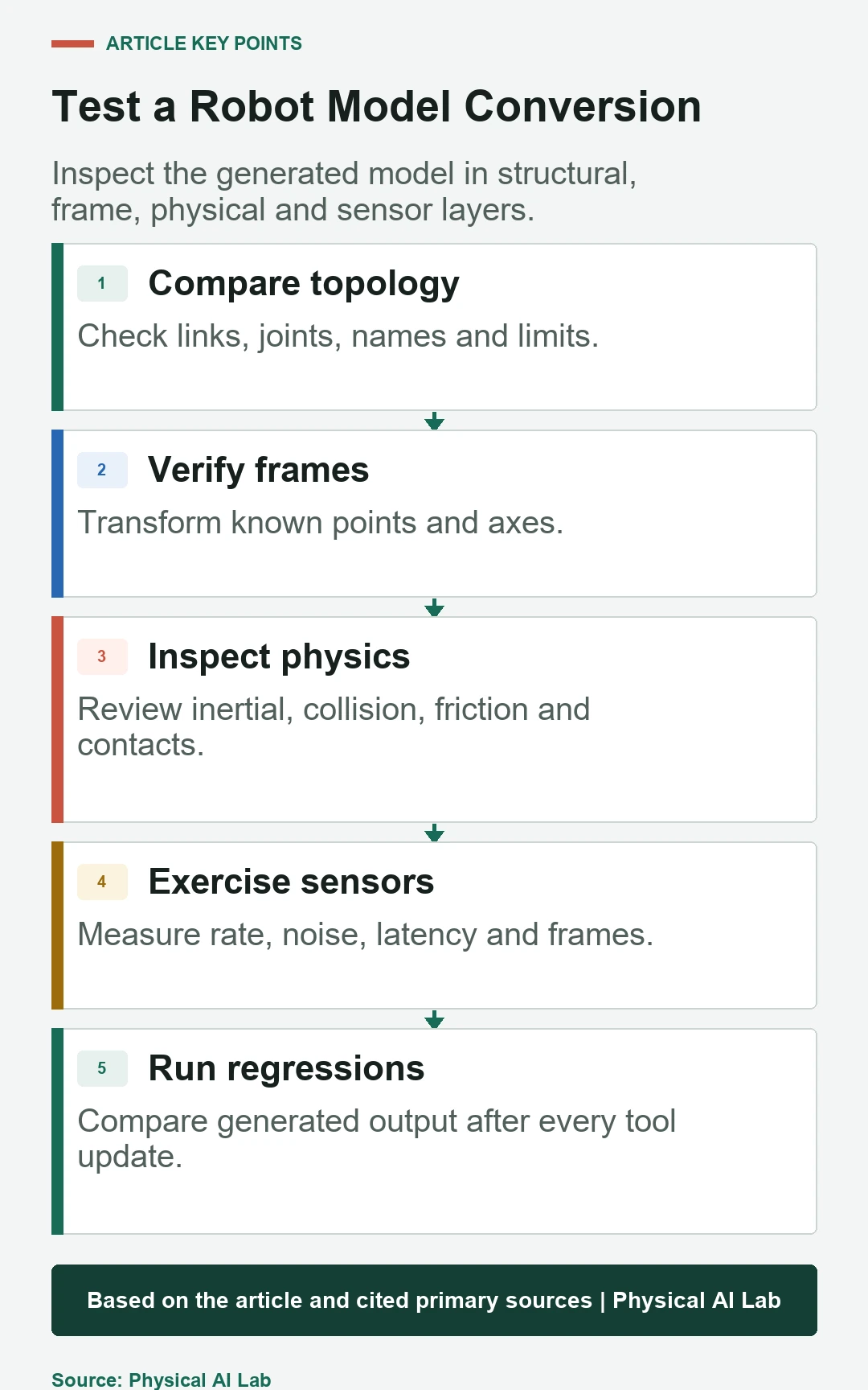
| Structure | Link and joint graph | Dropped fixed joint | Name and topology diff |
| Frames | Known poses and axes | Inverse or resolved pose | Transform probes |
| Physical | Mass, inertia and collision | Default or invalid value | Dynamic response |
| Sensors | Rate, noise, latency and frame | Plugin default | Recorded output |
| World | Gravity, friction and placement | Version-dependent setting | Scenario regression |
Use SDFormat worlds for reproducible scenarios
A world should specify environmental elements that affect the test: gravity, ground, friction, lighting, models, initial poses and physics configuration. External launch scripts can add variability, but their parameters and seeds must remain part of the scenario record.
Separate a reusable robot model from world-specific placement. Avoid embedding one warehouse assumption inside the robot asset. Version models and worlds independently and pin compatible combinations for regression tests.
Validate sensor behavior, not just presence
A sensor element can define type, update rate, pose, noise and rendering or physics parameters. Plugins bridge simulator data into ROS. A topic appearing proves connectivity, not that sampling time, field of view, noise or frame matches the physical device.
Compare simulated output with a sensor contract. Measure rate, timestamp, latency, frame_id, range limits and noise distribution. Use the SDFormat sensor specification for the declared version.
Treat Gazebo extensions as explicit dependencies
URDF often contains gazebo extension tags for materials, friction, sensors and plugins. They are practical when ROS tooling consumes URDF and Gazebo needs additional data. They also couple the source to specific conversion and simulator behavior.
Document every extension and test whether other URDF consumers ignore it safely. Keep simulator-only configuration grouped and generated where possible. A parameter silently ignored after an upgrade can change dynamics without invalidating XML.
Inspect the generated SDFormat
When a URDF is spawned in Gazebo, conversion produces an SDFormat representation. Fixed joints may be reduced or preserved according to rules, and extensions are mapped. The generated output, not the source URDF alone, determines simulator behavior.
Use the Gazebo URDF spawning documentation and conversion inspection tools for the deployed version. Diff generated SDFormat after upgrades and review warnings rather than assuming successful spawn means full fidelity.
Maintain one semantic source with generated targets
A practical project can maintain canonical parameters for geometry, joints, sensors and identifiers, then generate URDF and SDFormat targets for their consumers. This reduces duplicated manual values while allowing format-specific capabilities.
The generator becomes part of the trusted toolchain. Pin versions, test output and prohibit hand edits to generated files. When one format cannot express a feature, record the divergence explicitly instead of hiding it in an undocumented patch.
Run structural, frame, physical and sensor regressions
Parse every generated model, compare names and topology, probe transforms, simulate known free-fall or pendulum behavior, check contacts and replay sensor tests. Include model spawn, controller connection and a short task scenario.
Golden screenshots are useful for appearance but insufficient. Store numeric baselines with tolerances and investigate every converter warning. A changed simulator may require intentional baseline updates with physical justification.
Select format from commissioning evidence
Use URDF when the primary contract is ROS robot structure and supported extensions are sufficient. Use native SDFormat when worlds, nested models, sensors and simulator physics are primary. Many systems use both through controlled generation.
Base acceptance on the test scope rather than file extension.
- List every consumer and supported format version.
- Separate visual, collision and inertial evidence.
- Probe frames after every conversion.
- Test physics and sensors numerically.
- Version generators and generated artifacts together.
Frequently asked questions
Must a project choose only URDF or only SDFormat?
No. Many projects keep a semantic source and generate tool-specific URDF and SDFormat artifacts.
Can URDF describe sensors?
Simulator-specific extensions can add sensors, but native support and portability depend on the consuming tool.
Does a successful Gazebo spawn prove conversion is correct?
No. Frames, inertia, collision, plugins and sensor settings can still be wrong or ignored.
Can robot_state_publisher read SDFormat directly?
Its normal contract is URDF; use a supported conversion or generated URDF for that consumer.
What should a model regression test first?
Start with link and joint identity, then frames, inertial and collision behavior, sensors and complete scenarios.
Robot Model Fidelity Boundary
A robot model is an approximation tied to a toolchain and test purpose. Validate generated artifacts against physical measurements before using simulation results for operational claims.