Humanoid foot sensing estimates how the ground loads each foot and whether the contact is usable for state estimation and balance control. A six-axis force-torque sensor can measure a resultant wrench near the ankle, while pressure cells or distributed sensors reveal how load moves across the sole.
Ground reaction force, center of pressure and contact state are related but not interchangeable. A finite CoP value becomes unstable near zero normal force, and a loaded foot can still rock, slide or touch only at an edge. Each output needs its own validity conditions.
Use this guide with the force-torque sensor guide and humanoid state-estimation guide. Validate the mechanical load path, sensor, transform, filter and controller interface together.
Trace the mechanical load path first
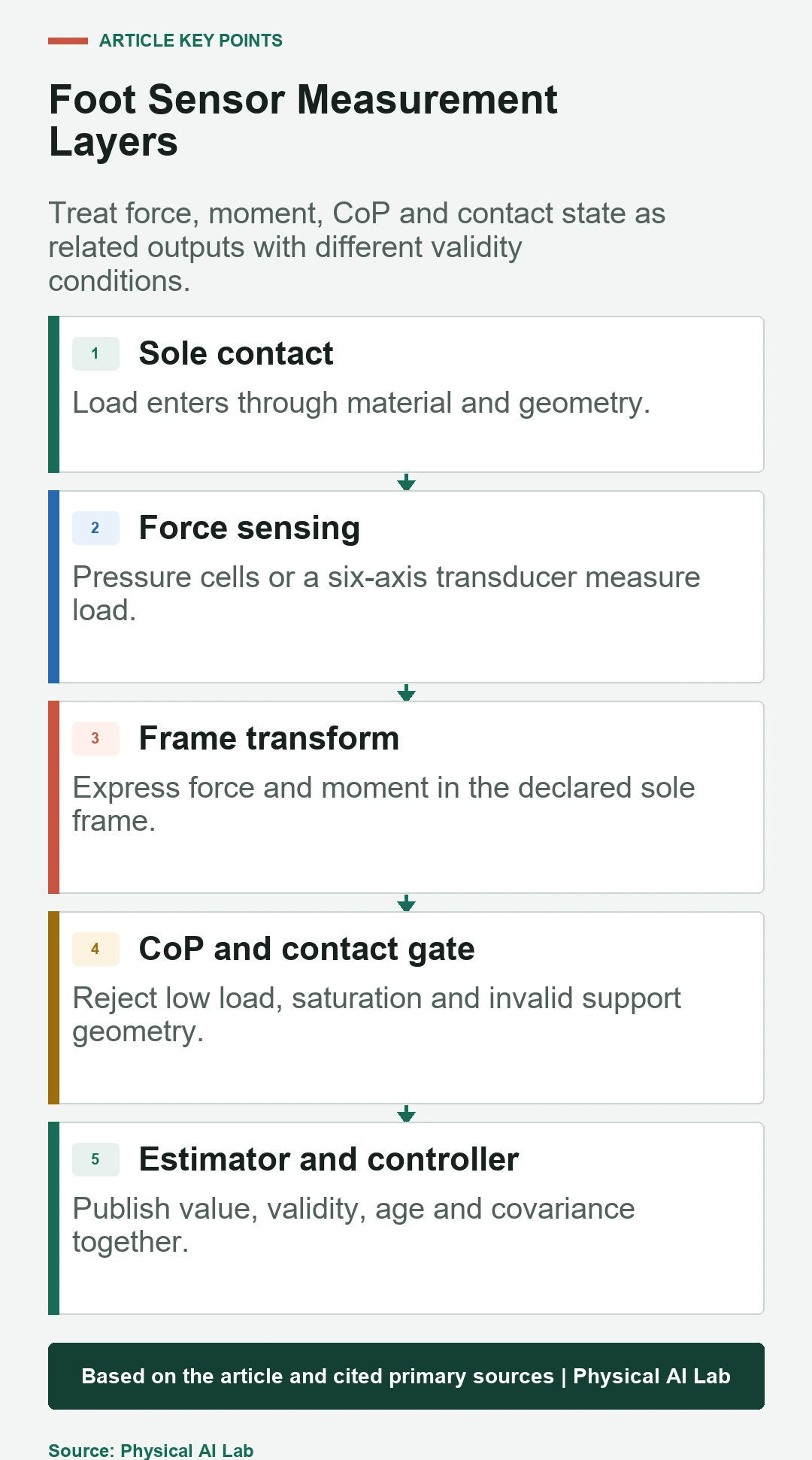
Ground load passes through sole material, compliant structures, fasteners and the sensor before reaching the leg. Bypass paths, cable strain and chassis contact can carry force around the intended transducer. Mechanical installation therefore defines what the electrical output represents.
Inspect preload, bolt torque, hard stops and temperature. Apply known loads at multiple sole locations and directions to confirm that the measured wrench follows the physical load path without unexpected hysteresis.
Choose sensing architecture from the required outputs
An ankle six-axis transducer measures net force and moment over a broad range but does not directly show local pressure. Distributed pressure sensing can reveal contact patches and local center of pressure but may have lower bandwidth, drift or cell-to-cell variation.
Hybrid designs can improve observability while adding calibration and synchronization work. The NASA Valkyrie foot design report is a useful hardware reference, but its mechanical choices are not a generic performance guarantee for other humanoids.
| Architecture | Direct evidence | Strength | Primary limitation |
|---|---|---|---|
| Ankle six-axis | Net force and moment | Compact wrench estimate | No local pressure map |
| Pressure array | Load distribution | Contact patch and CoP | Cell drift and bandwidth |
| Corner load cells | Discrete normal loads | Simple CoP estimate | Limited shear evidence |
| Joint torque estimate | Leg load proxy | No foot sensor required | Model and friction error |
| Hybrid | Wrench plus distribution | Cross-checking | Calibration complexity |
Declare sensor and sole frames
Force and moment depend on axis direction and reference point. Transforming a wrench between the sensor origin and sole plane changes moment through the lever arm. A sign error can mirror CoP or make a valid load appear outside the foot.
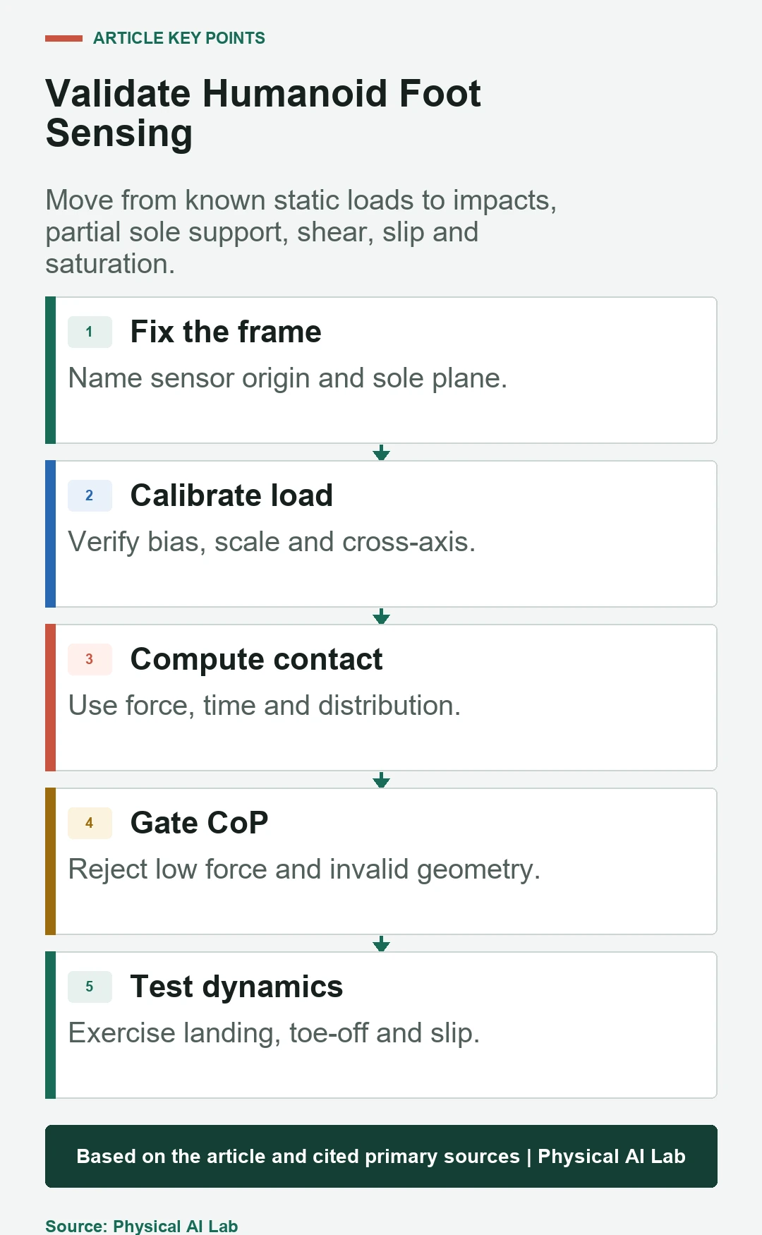
Publish the origin, axes, units and transform version with data. Verify positive normal force, known horizontal loads and moments produced by weights at measured sole coordinates before dynamic walking tests.
Calibrate bias, scale and cross-axis coupling
Zero-load bias alone is not calibration. Apply several known magnitudes and directions throughout the expected range, including combined loads. Fit or verify scale, offset, cross-axis terms and temperature dependence, then reserve separate trials for validation.
Repeat after assembly changes and warm-up. A sensor can be linear on a bench but show installation-induced coupling or preload once mounted inside the foot.
Compute CoP only when the equation is valid
For a declared contact plane, center of pressure is derived from moment divided by normal force, with signs and origin determined by the frame convention. As normal force approaches zero, noise and bias are amplified and the result becomes physically meaningless.
Gate CoP by minimum normal load, saturation, contact geometry and sensor health. Mark the output invalid instead of clamping it to the sole boundary, because clamping hides the condition that the measurement model has failed.
Distinguish contact detection from CoP validity
Touchdown can be detected from force rise, pressure distribution, planned phase and kinematic evidence. CoP may remain unreliable during the first impact samples or a small toe contact. Liftoff likewise passes through a low-load interval before the foot is clearly airborne.
Use a contact state machine with hysteresis and dwell. Provide states such as airborne, impact, loaded support, partial contact and unloading when downstream estimation or control needs different assumptions.
Handle partial sole and edge contact
On a stair edge or uneven surface, only part of the sole may carry load. The resultant CoP can still lie inside the nominal foot polygon while the actual support region is smaller and the allowable moment is reduced.
Use pressure or terrain geometry to estimate the active support polygon when the application permits partial contact. Otherwise reject the condition and command unloading or a corrective step.
Measure dynamic bandwidth and impact response
Walking introduces impacts, vibration and fast load transfer that static weights do not test. Mechanical resonance, digital filtering and communication delay change the timing and amplitude seen by the controller. An attractive smooth trace can be late.
Apply controlled impacts and representative gait cycles, then measure frequency response, delay, overshoot and saturation recovery. Preserve raw samples so filter changes can be evaluated without repeating every hardware trial.
Detect saturation, clipping and overload
A clipped force channel can corrupt moments and CoP even when the remaining channels look plausible. Overload can also leave a permanent zero shift or damage a pressure cell. Saturation flags need to travel with the derived outputs.
Test near the qualified range with approved fixtures, never by unsafe impacts. Define whether the robot unloads, stops or switches to a degraded estimator when a channel saturates or becomes implausible.
Fuse force with kinematic and inertial evidence
Force indicates load but does not prove that the foot is stationary. Kinematics, IMU, foot velocity and terrain perception help distinguish stable support, rocking and slip. Distributed pressure can show a moving contact patch before gross motion becomes large.
The 2026 CoP self-calibration study examines automatic calibration under its stated setup. Keep sensor design, robot and experimental scope explicit before applying its conclusions elsewhere.
Evaluate control usefulness, not sensor error alone
Report force and moment error, CoP error, contact detection delay, false transitions, bandwidth, saturation and drift. Then measure balance, foot-placement and safe-mode behavior when the data is used by the controller.
Use the humanoid balance guide to define downstream quantities. Compare raw, filtered and rejected intervals so a controller improvement is not credited to hidden removal of difficult data.
| Test condition | Sensor metric | Derived metric | Control evidence |
|---|---|---|---|
| Static load | Force and moment error | CoP position | Posture stability |
| Touchdown | Peak, delay, saturation | Contact latency | Torque transient |
| Toe or edge | Load distribution | Active support | Balance margin |
| Slip | Shear and pressure motion | Contact validity | Recovery command |
| Thermal run | Bias and scale drift | CoP drift | False correction |
Release with a foot-sensing contract
Document mechanical load path, sensor model, range, frames, calibration, filter delay, CoP equation, validity gates, contact states and fault response. Keep calibration fixtures, raw data and software versions with the acceptance record.
Close validation with the following checklist.
- Verify the installed mechanical load path.
- Calibrate scale, bias and cross-axis coupling.
- Declare wrench frames and sole-plane conventions.
- Reject CoP at low load, saturation and invalid geometry.
- Test static, impact, partial-contact, slip and thermal cases.
Frequently asked questions
Are foot force and center of pressure the same quantity?
No. Force is a load vector; CoP is a derived point whose validity depends on normal load, moment, frame and contact geometry.
Why does CoP jump near liftoff?
Its calculation divides moment by a small normal force, so sensor noise and bias are greatly amplified.
Does a loaded foot mean it is stationary?
No. A loaded foot can rock or slide; combine force with kinematics, inertial sensing, pressure motion or external observation.
Is static weight calibration sufficient?
No. Walking also requires impact bandwidth, delay, saturation, partial-contact and temperature validation.
What should happen when CoP is invalid?
Publish an explicit invalid state and let estimation or control use a tested degraded policy rather than a fabricated boundary value.
Loaded-Contact and Valid-CoP Boundary
CoP is a conditional measurement, not an always-available coordinate. Low load, saturation and partial support must propagate as validity information to estimation and control.