Humanoid state estimation reconstructs the floating base pose, velocity, IMU bias and contact state that walking control cannot measure directly. Joint encoders describe the mechanism internally, but they do not place the pelvis or feet in the world without an external or contact-based constraint.
An IMU provides high-rate angular velocity and specific force, yet integration accumulates bias and noise. Foot kinematics can correct drift while a contact is fixed. The same update becomes harmful when the foot slips, rocks or is incorrectly classified as supporting.
Use this guide with the IMU bias and calibration guide and coordinate-frame guide. Evaluate estimator consistency and its effect on balance control, not pose error alone.
Define the state and every output contract
A typical state includes base orientation, position, velocity, gyroscope bias, accelerometer bias and one or more contact locations. Some systems also estimate gravity direction, foot orientation, sensor scale or terrain parameters. State choice determines what can be observed and which errors can be corrected.
Publish timestamp, frame, covariance, contact confidence and validity with the numeric state. A controller that receives a fresh-looking pose without data age or uncertainty cannot distinguish a good estimate from delayed or degraded operation.
Propagate the state with the IMU model
The gyroscope propagates orientation, and accelerometer specific force is rotated and combined with gravity to propagate velocity and position. Bias, scale, axis alignment, temperature and vibration enter this prediction directly. Small persistent errors grow through integration.
Use calibrated units and a documented IMU-to-base transform. Apply measurements at their acquisition times, preserve covariance growth and avoid pretending that a high update rate removes low-frequency bias.
| Input or state | Provides | Dominant risk | Validation evidence |
|---|---|---|---|
| Gyroscope | Angular-rate propagation | Bias and vibration | Static and motion residual |
| Accelerometer | Specific-force propagation | Gravity and scale error | Orientation sweep |
| Joint encoders | Base-to-foot kinematics | Zero and compliance error | Kinematic closure |
| Foot contact | World constraint | Slip or false support | Force and motion evidence |
| External pose | Global correction | Latency and frame bias | Timed residual |
Use joint kinematics to connect base and feet
Encoder measurements and the robot model provide the transform and velocity between the floating base and each foot. If a foot is fixed in the world, that relative motion constrains base velocity and pose. Model error and structural compliance limit the accuracy of this correction.
Verify joint zero, link dimensions, axis directions and foot frames under load. A kinematic chain that closes in simulation may shift when the sole compresses or the structure flexes during single support.
Treat contact as a probability, not a perfect switch
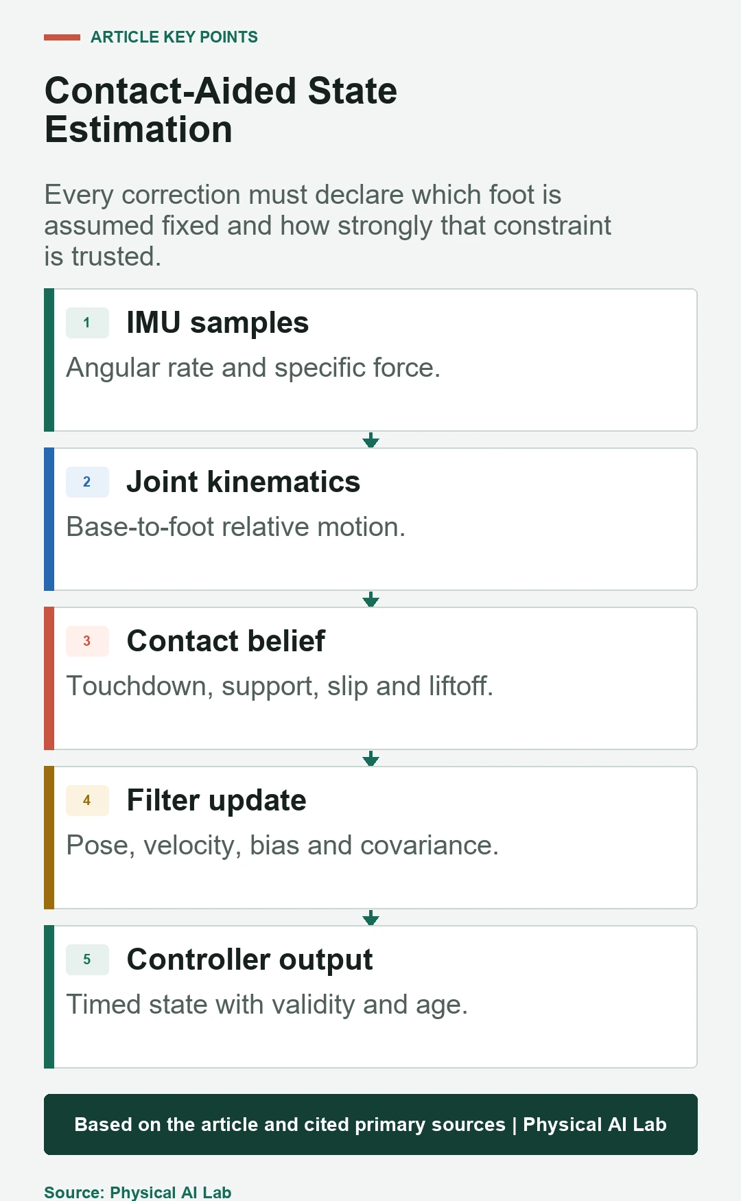
Touchdown and liftoff take time, and partial contact can move the effective support point. Combine planned gait phase with force, kinematics and foot-motion evidence. Hysteresis and dwell can prevent rapid switching near a threshold.
Associate separate confidence and covariance with each contact. Do not make both feet perfectly fixed during a transition merely because two force readings exceed a nominal number.
Apply contact-aided filter corrections consistently
A contact-aided estimator adds or activates a contact landmark and uses the expected stationary-foot motion to correct the propagated state. The Contact-Aided Invariant EKF paper develops this formulation and analyzes observability for legged robots.
Implementation still requires explicit noise, contact creation and removal, timestamp handling and frame definitions. Compare filter consistency as well as mean error; an estimator can be numerically smooth yet unjustifiably confident.
Reject slipping or rocking contacts
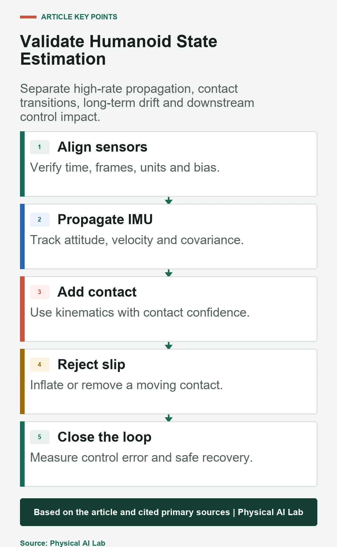
If a supporting foot moves while the filter assumes it is fixed, the estimated base moves in the opposite direction. This can corrupt center-of-mass velocity and the next foothold before slip becomes visually obvious.
Monitor contact innovation, tangential force, foot velocity, sole pressure distribution and external motion where available. Inflate contact covariance or remove the constraint when evidence leaves the qualified stationary-contact envelope.
Understand what remains unobservable
IMU and contact kinematics do not necessarily provide global position or absolute yaw. Repeated contact can constrain relative motion without creating an external world reference. An estimator should allow uncertainty to grow in unobservable directions instead of hiding drift.
Add vision, lidar, GNSS or fixed markers when the task needs a global reference. Define how delayed or intermittent global measurements enter the filter without producing discontinuities that destabilize control.
Align clocks, frames and gravity before tuning
IMU, encoders, force sensors and external pose often run at different rates and arrive with different delays. A few milliseconds of offset near impact can look like a model failure. Process measurements by acquisition time and preserve bounded buffering or state rewind behavior.
Name IMU, base, pelvis and foot frames with transform direction and handedness. Estimate gravity only under defensible motion conditions, and test startup orientation rather than assuming the robot always boots upright.
Handle impact, vibration and saturation
Foot strike creates high-frequency acceleration and structural vibration. Filtering can reduce noise but also delay the estimate through the phase where the controller needs it most. Sensor range and mounting resonance matter as much as nominal noise density.
Log raw and filtered data, saturation flags and filter delay. Test normal walking, hard landing, heel or toe contact and protective stops. The legged state-estimation study illustrates learned contact estimation, but learned confidence still needs out-of-distribution and fault validation.
Make external corrections bounded and explainable
Vision or lidar can arrest position and yaw drift, but a delayed loop closure or map mismatch can create a large state jump. Gate residuals, account for measurement age and define whether controllers receive a reset, a smooth correction or a separate global frame.
Test temporary loss, relocalization and a plausible false match. A global sensor should improve observability without becoming a single unmonitored source of discontinuous motion.
Evaluate transitions and downstream control
Segment metrics by standing, single support, double support, touchdown, liftoff, turning, disturbance and slip. Report orientation, position and velocity error, bias convergence, innovation, covariance consistency and recovery time.
Connect the estimate to the humanoid balance controller and log command consequences. A small base-velocity error can be more damaging than a larger global position error if it changes a capture step.
| Test condition | Estimator metric | Control metric | Failure injection |
|---|---|---|---|
| Standing | Bias and drift | Posture motion | Warm start |
| Walking | Velocity and pose error | Foot placement error | Timing offset |
| Transition | Innovation and jump | Torque or CoM transient | Contact delay |
| Slip | Detection and consistency | Recovery latency | Low friction |
| Sensor fault | Covariance and validity | Safe-mode entry | Freeze or dropout |
Release with an estimator acceptance checklist
Document state definition, frames, timestamp policy, IMU calibration, contact model, noise, observability, external correction and degraded behavior. Store raw synchronized data and software configuration with each benchmark.
Close validation with the following checklist.
- Calibrate IMU and kinematic frames under load.
- Publish covariance, validity and data age.
- Model contact transitions and slip explicitly.
- Preserve uncertainty in unobservable directions.
- Test estimator error and balance-control outcome together.
Frequently asked questions
Can joint encoders alone estimate the humanoid base pose?
Only relative to a correctly modeled fixed contact; they do not independently provide a global floating-base pose.
Why does IMU integration drift?
Bias, noise, gravity error and scale or alignment error accumulate when angular rate and acceleration are integrated.
Does a foot-force threshold prove stationary contact?
No. It indicates load, but the foot may rock or slip; combine force with kinematic, pressure and motion evidence.
Should covariance stay small during walking?
Only where measurements make the state observable and consistent; uncertainty should grow when constraints disappear or become unreliable.
What is the most important validation interval?
Touchdown, liftoff and slip, because the contact assumption changes and estimation errors can immediately affect control.
Trusted-Contact and Observable-State Boundary
A contact correction is safe only while its stationary-foot assumption remains credible. Remove or weaken the constraint before confident drift becomes a control command.