A motor-side encoder measures the actuator before the gearbox and supports commutation and fast velocity control. A load-side encoder measures the joint output after transmission. Comparing them can expose backlash, elastic twist and transmission error, provided ratio, direction, zero and timestamps are correct.
The second sensor does not eliminate mechanical error. It supplies output feedback that an outer position loop or observer can use. Aggressive load-side bandwidth can excite gearbox compliance and amplify quantization, delay or structural resonance.
Use this guide with the robot encoder guide and system identification guide. Commission geometry and diagnostics before closing the outer loop.
Know what one motor encoder cannot observe
Motor angle divided by nominal ratio estimates output angle only when gear geometry is ideal. Backlash, compliance, hysteresis, bearing motion, assembly error and load deformation occur after the motor sensor. They can change end-effector position while motor control appears accurate.
List the accuracy budget from motor sensor through gearbox, joint and links. Add a load encoder where direct joint information materially improves control, calibration or fault detection.

Keep motor feedback responsible for fast inner control
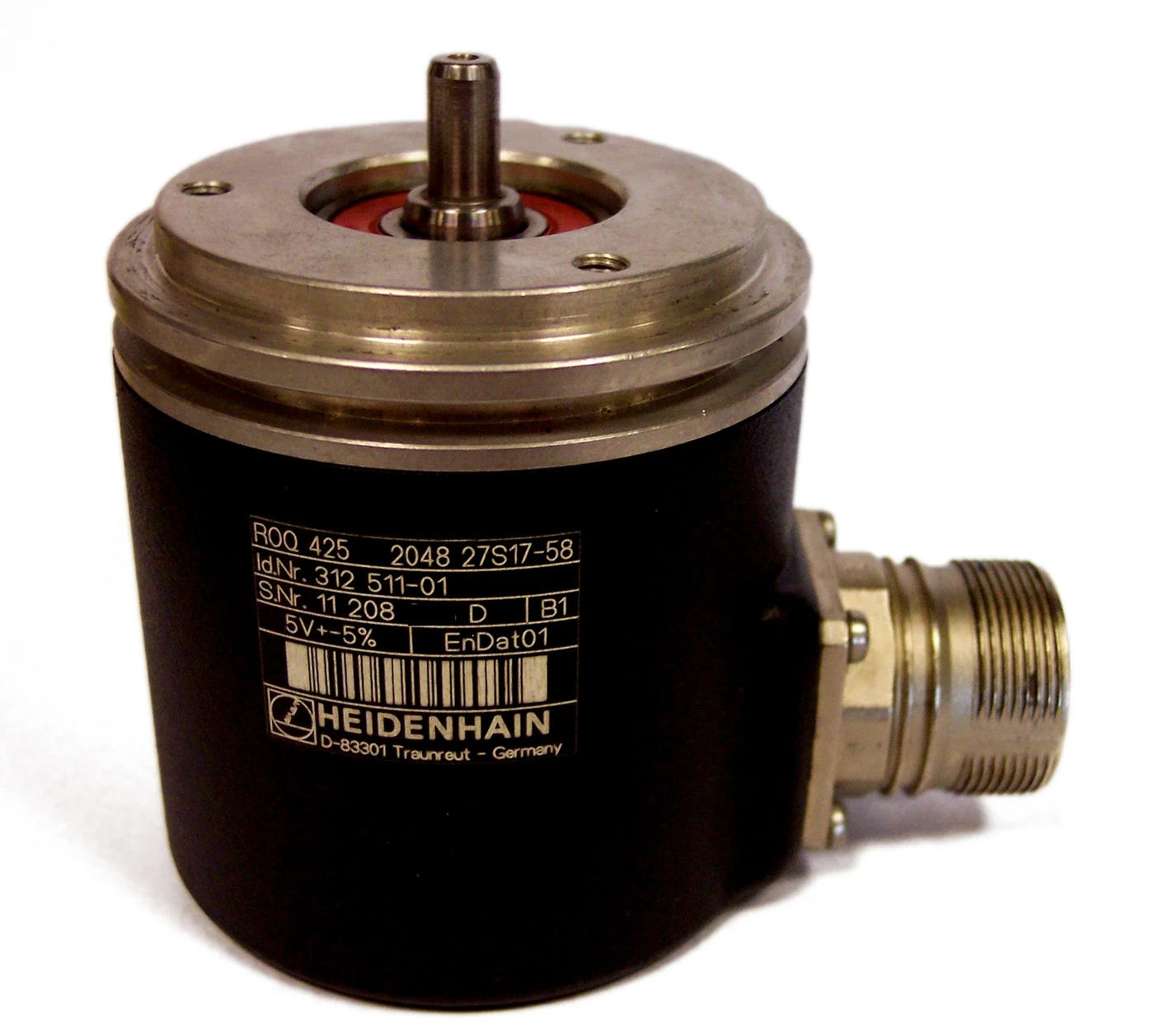
The motor encoder usually provides electrical angle or rotor position for commutation and high-bandwidth velocity or position control. Its rigid connection and high effective output resolution after gearing support fast disturbance rejection.
Do not make motor commutation depend on a delayed load sensor through compliant transmission. Current drive products may support separate commutation and load encoders; the ODrive encoder documentation illustrates this distinction for its hardware.
| Feedback | Physical location | Primary strength | Primary blind spot |
|---|---|---|---|
| Motor encoder | Rotor or input shaft | Fast commutation and velocity | Gearbox output error |
| Load encoder | Joint output | Direct joint position | Motor commutation |
| Difference signal | Ratio-aligned pair | Transmission behavior | Mounting and time errors |
| External metrology | Link or end effector | Independent accuracy check | Continuous embedded control |
| Torque sensor | Transmission or joint | Load and compliance evidence | Absolute position |
Measure output position after the transmission
Mount the load encoder so it follows the true joint output with minimal intervening compliance. Define the mechanical datum, bearing relationship and thermal expansion path. A sensor attached to a flexible cover may report cover motion rather than joint angle.
Select absolute or incremental behavior, resolution, accuracy, update rate and interface for the task. Validate installation eccentricity, tilt and air gap according to supplier requirements.
Express both angles in one coordinate frame
Apply gear ratio, sign, units, rollover and joint direction before subtracting signals. Use the actual calibrated ratio when manufacturing error matters. Handle multi-turn state and homing consistently across reboot.
Compare several known poses and full rotations. A sign or ratio error can look like growing compliance, while an off-by-one multi-turn state appears as a sudden transmission fault.
Include encoder mounting error in the difference
Code-disk eccentricity, sensor-head alignment, shaft runout, coupling error and bearing motion add periodic or load-dependent error. Both encoder specifications and mechanical installation therefore enter the transmission difference.
Use reversal, slow rotation and independent metrology to separate periodic sensor error from gearbox behavior. Do not label every repeatable harmonic as gear stiffness.
| Observed difference | Possible cause | Discriminating test | Control risk |
|---|---|---|---|
| Dead zone on reversal | Backlash or stiction | Bidirectional slow sweep | Limit cycle |
| Proportional to torque | Elastic twist | Known load sweep | Outer-loop resonance |
| Periodic with angle | Encoder or gear error | Independent metrology | Tracking ripple |
| Grows with speed | Timestamp or filter delay | Time-alignment test | Phase loss |
| Sudden step | Slip, rollover or dropout | Raw state and index check | Unsafe command jump |
Identify backlash during direction reversal
Backlash appears when motor motion changes direction while output initially remains still. Friction and compliance can blur the boundary. Measure at several loads, speeds and temperatures rather than reporting one angular number.
A controller can compensate predictable lost motion, but compensation does not remove impact, wear or direction-dependent uncertainty. Limit aggressive reversal commands and validate stability.
Identify elastic twist as a dynamic state
Under torque, transmission compliance produces a continuous motor-to-load angle difference. Stiffness can be nonlinear and frequency dependent. Damping, friction and structural modes shape recovery after load changes.
Estimate stiffness with known torque and synchronized angles. Excite only safe amplitudes. Use frequency response to locate resonances before setting outer-loop bandwidth.
Use nested loops with intentional bandwidth separation
A common design keeps fast current and motor velocity control inside a slower load-position loop. The outer loop commands the inner loop while observing actual joint output. Bandwidth separation helps avoid fighting compliant dynamics.
The Synapticon dual-loop explanation describes this control concept. Tune the deployed plant from measured delay, resonance and noise rather than copying gains.
Balance load feedback against noise and resonance
Higher load-side gain improves low-frequency accuracy but exposes quantization, sampling delay and mechanical resonance. Filtering reduces noise while adding phase lag. Check worst communication jitter and the effect of stale samples.
Measure sensitivity, tracking and disturbance response across payload and temperature. Keep saturation and anti-windup behavior visible during large errors.
Calibrate zero, ratio and time before control
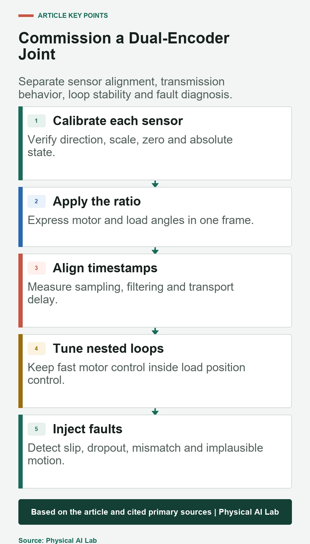
Perform independent sensor validity checks, establish a joint datum, align directions and scale, and measure relative timestamp delay. Store calibration identity and temperature. Reject an unknown absolute state on startup.
Move slowly through the range and verify the residual is plausible before enabling torque. A timing error during acceleration can create an apparent elastic angle large enough to trigger false faults.
Use disagreement as a diagnostic with context
Persistent mismatch can indicate sensor slip, gearbox damage, excessive deflection or calibration loss. Diagnostic thresholds should depend on torque, speed, direction and temperature. A fixed small limit may false-trigger under normal load.
Inject dropout, frozen value, sign error and mounting slip. Define whether the joint stops, degrades or continues. Redundant signals do not automatically provide fault tolerance without independence and a validated decision policy.
Validate accuracy, stability and fault response together
Measure joint and end-effector accuracy, reversal behavior, compliance, frequency response, tracking, sensor age and diagnostic coverage. Repeat across payload and thermal conditions. Save raw signals, not only the fused estimate.
Release with a concise checklist.
- Align ratio, direction, zero and timestamps.
- Measure mounting and transmission error separately.
- Keep fast motor control inside load-position control.
- Tune below measured compliant resonances.
- Inject sensor and mechanical disagreement faults.
Frequently asked questions
Why not use only the load-side encoder?
Motor feedback is normally needed for commutation and fast control; load feedback observes output position across the transmission.
Do dual encoders remove backlash?
No. They reveal output error and enable compensation or control, but mechanical backlash remains.
Is the encoder difference entirely gearbox compliance?
No. Ratio, zero, timestamps, mounting, sensor error, friction and backlash also contribute.
How fast should the outer load-position loop run?
Set it from measured delay, noise and resonances with adequate separation from inner loops; no universal rate applies.
Can a robot continue after one encoder fails?
Only if the architecture has validated fault detection, safe degradation and sufficient remaining feedback for that operating mode.
Feedback Accuracy and Control Stability Boundary
Dual feedback can improve control and diagnostics but is not automatically safety-rated redundancy. Validate failure independence and the robot's safe response.