Motor current can estimate the electromagnetic torque produced inside a robot actuator. It does not directly measure the external torque at the joint. The estimate must cross a calibrated motor torque constant, transmission model and robot dynamics before it can represent output or contact torque.
Use measured torque-producing q-axis current rather than an unverified current command. Then account for sensor offset, sign, motor temperature, gear ratio, direction-dependent efficiency, gravity, inertia and friction. Voltage saturation or current clipping can invalidate the assumed relationship even when the equation looks correct.
Use this guide with the robot force-torque sensor guide, joint friction guide and system-identification guide. Treat current-derived torque as a model-based estimate with stated uncertainty, not as certified contact-force sensing.
Define which torque the application needs
Electromagnetic motor torque, gearbox input torque, joint output torque and external interaction torque are different quantities. A controller may need motor torque for inner-loop regulation, joint torque for load monitoring, or external torque for collision and contact estimation. Name the quantity, coordinate frame, sign and sample time before selecting an equation.
Also define whether the value is instantaneous, filtered, peak, continuous or averaged over a window. A low-pass estimate suitable for payload monitoring may be too delayed for contact detection. A fast residual may be too noisy for accurate static force reporting.
Document the intended decision as well as the unit. Displaying a number, limiting a command and triggering a protective stop require progressively stronger evidence and independence.

Start with measured q-axis current
In field-oriented control, q-axis current is normally the torque-producing current for a surface permanent-magnet motor under the controller’s conventions. Phase current, bus current, RMS current, peak current and current command are not interchangeable. Read the drive documentation and log the actual feedback signal with its scaling and sign.
Current-sensor offset creates a false torque at zero load, while gain error changes the slope. Switching ripple, ADC timing, dead time and filtering affect bandwidth. Capture raw or minimally processed current during commissioning so later filters do not hide the measurement source.
| Logged value | What it represents | Common error | Required check |
|---|---|---|---|
| Current command | Requested controller action | Clipping or tracking error | Compare with measured current |
| Measured q-axis current | Torque-producing current estimate | Offset, sign or scale | Zero-current and reference-current test |
| Phase current | Per-phase electrical current | Transform convention | Verify Clarke-Park implementation |
| DC-bus current | Power-source current | Confused with motor torque | Use only with voltage and efficiency model |
| Filtered current | Bandwidth-limited signal | Hidden delay | Measure magnitude and phase response |
Calibrate the motor torque constant
The ideal relation is motor torque equal to torque constant times q-axis current. Catalog torque constant may use peak or RMS current, line-to-line or phase conventions, and a specified temperature. A convention mismatch can create a fixed scale error that survives every software test.
Calibrate the installed actuator with known reaction torque or output force at several positive and negative currents. Fit offset and slope only inside the verified linear range. Repeat after thermal stabilization because magnet flux, winding resistance and current-control margin change with temperature.
Map motor torque through the transmission
For an ideal reducer, output torque scales with gear ratio. Real output also depends on efficiency, which varies with torque, speed, direction, temperature, lubrication and whether the load drives the motor. Backdriving and motoring can therefore need different mappings.
Include bearing, seal and cable forces if they lie between the motor and the desired output boundary. Validate signs in all quadrants: positive and negative speed crossed with positive and negative torque. A single scalar efficiency is acceptable only inside the envelope where testing supports it.
Separate internal dynamics from external torque
Current supplies torque for gravity, acceleration, friction and external interaction. A common residual subtracts modeled gravity, inertia, Coriolis or centrifugal effects and friction from the current-derived joint torque. The remainder is interpreted as unmodeled or external torque.
This residual is not pure contact. Payload error, flexible cables, gearbox hysteresis, structural vibration and model mismatch also appear in it. The peer-reviewed collision-detection study shows how momentum or disturbance observers can use model residuals, but deployed thresholds still require robot-specific validation.
| Residual component | Typical signature | Useful experiment | Risk if omitted |
|---|---|---|---|
| Gravity error | Pose-dependent bias | Slow pose grid with known payload | False contact in some poses |
| Inertia error | Acceleration-correlated peak | Bidirectional trajectory sweep | False collision during motion |
| Friction | Speed and direction dependence | Constant-speed reversals | Biased low-speed torque |
| Transmission hysteresis | History-dependent difference | Load and unload cycle | Nonrepeatable threshold |
| External contact | Task-dependent sustained or impulsive residual | Instrumented contact trials | Missed or late detection |
Identify gravity and payload before thresholding
Gravity torque depends on joint pose, link mass, center of mass and payload. A payload change can look exactly like a sustained external force. Estimate or identify payload properties, and reject torque judgments when configuration data are missing or inconsistent.
Collect slow trajectories in both directions so inertial torque is small. Compare the current-derived torque with rigid-body gravity prediction across the workspace. Hold out poses from fitting to test whether the model generalizes rather than merely memorizes calibration points.
Model inertia without amplifying encoder noise
Inertial torque depends on acceleration and coupled robot dynamics. Numerical differentiation of encoder position can amplify quantization and noise, while heavy filtering delays the estimate. Prefer synchronized velocity and acceleration estimates with documented filter latency.
Excite representative accelerations and payloads within safe limits. Use the joint actuator testing workflow to compare requested, measured and reference quantities. Check residuals during both acceleration and deceleration because sign errors can cancel in only one direction.
Treat friction as a state-dependent uncertainty
Friction includes stiction, Coulomb, viscous, seal, bearing and transmission effects. It can depend on speed, direction, position, temperature, load and motion history. Near zero speed, the same measured current may support a range of torque before motion begins.
Fit friction using dedicated trajectories and validate on separate cycles. The friction-compensation guide explains why one constant offset is rarely sufficient. Keep a confidence band around zero-speed estimates instead of forcing a precise but unsupported value.
Detect saturation and loss of linear authority
At high speed, available bus voltage may be insufficient to track requested current. Current limits, thermal derating and inverter protection can also clip the response. The command-to-torque relationship then fails, although the measured current may still report the torque that was actually produced within sensor accuracy.
Log voltage utilization, current-tracking error, limit states and faults beside the estimate. The ODrive control documentation is one example of a drive interface that distinguishes controller signals and limits. Mark output invalid or lower its confidence when the calibrated operating envelope is exceeded.
Use temporal evidence for contact detection
A collision detector should consider residual magnitude, duration, rate of change, direction and robot state. A high impulse during commanded acceleration is different from a persistent residual during a static hold. Hysteresis and debounce can reduce chatter but also add detection delay.
Build thresholds from labeled no-contact and contact trials across pose, payload, speed and temperature. Report false-positive and false-negative rates plus detection time. Never tune only on the dramatic contact cases that are easiest to separate.
Add output feedback when transmission error matters
A motor encoder cannot observe all backlash, compliance or output-side disturbance. A load-side encoder can expose transmission twist and improve the state estimate when its ratio, zero and timestamps are aligned. Read the dual-encoder guide before interpreting motor-to-load angle as torque.
If stiffness is known and locally valid, elastic deflection can provide another torque estimate. Compare it with current-derived torque and an independent reference. Disagreement is diagnostic evidence, not a reason to average signals blindly.
Validate against an independent torque reference
Use calibrated weights and lever arms for static checks, then a torque transducer, force-torque sensor or calibrated load cell for dynamic checks. Verify fixture compliance, lever geometry, alignment, sensor bandwidth and uncertainty. The Carnegie Mellon series-elastic actuator calibration paper illustrates how actuator sensing benefits from explicit calibration and comparison.
Test zero, scale, linearity, hysteresis, repeatability, bandwidth, thermal drift, payload changes and all motion quadrants. Save raw synchronized data and software version. Release the estimator only for the envelope supported by held-out trials.
Use a concise release checklist.
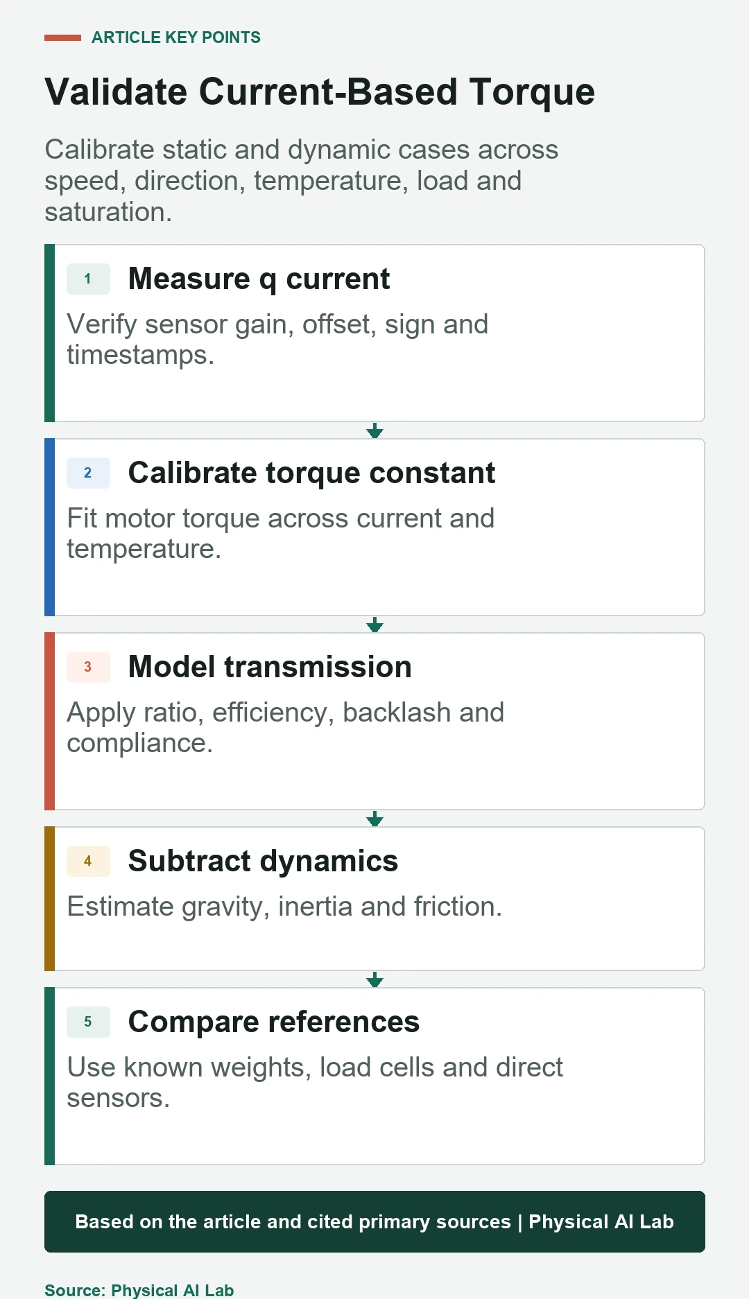
- Name the torque boundary and current convention.
- Calibrate current offset, torque constant and transmission mapping.
- Subtract validated gravity, inertia and friction models.
- Expose saturation, latency and confidence with every estimate.
- Compare against an independent reference across the operating envelope.
Frequently asked questions
Can motor current directly measure external joint torque?
No. It estimates motor electromagnetic torque; transmission losses and robot dynamics must be modeled before interpreting an external-torque residual.
Should I use commanded or measured current?
Use calibrated measured torque-producing current and log the command separately to detect tracking error and saturation.
Is the catalog torque constant accurate enough?
It can initialize a model, but current convention, installed hardware and temperature should be calibrated for the required accuracy.
Why does estimated torque change when the robot reverses?
Friction, backlash, gearbox efficiency, current offset and filtering can all be direction dependent.
Can current-based torque estimation replace a safety-rated force sensor?
Not by default. Safety functions require an architecture, diagnostics and validation appropriate to the applicable risk and standards.
Estimated Torque and Contact-Safety Boundary
Current-based torque estimation is model dependent. Do not claim contact-force accuracy or safety integrity beyond the independently validated operating envelope.