An IMU measures angular velocity and specific force. It does not directly measure global orientation, velocity or position. Those states emerge by integrating measurements and combining them with gravity, kinematic and external observations.
Gyroscope bias integrates into angle error. Accelerometer bias integrates into velocity error and then position error. Scale factor, axis misalignment, vibration, temperature, sampling and timestamp errors create different signatures and require different tests.
Use this guide with the robot sensor-fusion guide and robot coordinate-frame guide. Calibration values must be tied to the exact sensor, mount, firmware and operating envelope.
Interpret angular velocity and specific force correctly
A stationary gyroscope should ideally report zero angular rate. A stationary accelerometer on Earth does not report zero; it measures specific force associated with support against gravity, expressed in its sensor frame. Orientation estimates use this gravity direction only when other linear acceleration is sufficiently separated.
Define axis direction, handedness and units at the driver boundary. The official ROS sensor_msgs/Imu definition specifies orientation, angular velocity, linear acceleration and separate covariance arrays, but the message cannot prove that the underlying values are calibrated.
Log raw measurements before assuming an estimator output is a sensor truth.

Separate bias, noise, scale and alignment
Bias is an additive offset, noise varies sample to sample, scale error changes gain and non-orthogonality or misalignment mixes axes. A single zero subtraction cannot correct all four. Saturation, quantization and nonlinearity introduce further limits.
Create an error budget for each axis and temperature. The VectorNav IMU specification primer distinguishes several relevant noise and bias terms. Use the selected manufacturer’s definitions when comparing devices.
| Error | Static signature | Motion signature | Calibration evidence |
|---|---|---|---|
| Bias | Nonzero mean | Integrated drift | Long stationary log |
| Scale factor | Wrong gravity magnitude | Rate or acceleration gain error | Known force or rotation |
| Axis misalignment | Cross-axis component | Coupled motion | Multi-axis fixture |
| White noise | Sample scatter | Random walk after integration | Noise density and log |
| Temperature drift | Warm-up change | Mission-dependent bias | Thermal sweep |
Understand how gyro bias becomes attitude drift
A constant angular-rate offset accumulates approximately linearly into angle when uncorrected. Gravity can help constrain roll and pitch during suitable motion, but it does not directly observe yaw. Magnetometers, vision, lidar or other references may constrain heading with their own failure modes.
Measure yaw drift during long stationary holds and representative motion. Report drift distribution and temperature rather than one best run.
Accelerometer error grows quickly after integration
An acceleration offset changes estimated velocity continuously, and position error can grow quadratically in a simple uncorrected case. Small orientation error also projects gravity incorrectly into horizontal acceleration, often overwhelming true low acceleration.
Pure double integration is therefore not a practical long-term position solution for a typical robot IMU. External position, velocity, contact or zero-motion constraints are needed according to the application.
Calibrate accelerometers across six gravity poses
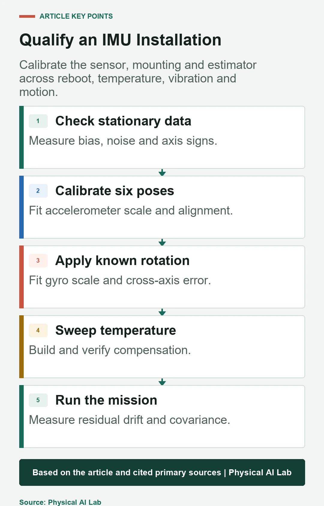
Place each sensor axis approximately along positive and negative gravity while the unit is stationary. Multiple orientations help fit offset, scale and cross-axis terms. Precise multi-position methods use more than six samples and an optimization model.
Reject samples with vibration or motion and use a stable reference surface. Verify the calibrated norm and direction on held-out orientations, not only the poses used for fitting.
Calibrate gyroscope scale with known rotation
Stationary data estimates gyro zero and noise but cannot determine rate scale accurately. Use a traceable turntable or another known angular displacement and time. Exercise positive and negative rates on each axis within the intended dynamic range.
Check linearity, cross-axis response and saturation. Mounting-fixture error enters the result, so fixture alignment and reference uncertainty belong in the report.
| Test | Primary parameter | Control variable | Acceptance output |
|---|---|---|---|
| Stationary hold | Bias and noise | Time and temperature | Mean, deviation, drift |
| Six or multi-pose | Accelerometer scale and axes | Gravity direction | Residual vector |
| Known-rate rotation | Gyro scale and axes | Reference rate | Gain and cross-axis |
| Thermal chamber | Temperature model | Soak and ramp | Held-out compensation error |
| Mission replay | Installed performance | Vibration and motion | State drift and consistency |
Model startup and temperature behavior separately
Power-on bias, warm-up transient, temperature hysteresis and run-to-run variation are not the same quantity. A compensation table fitted during heating may fail during cooling or after a different soak time. The mounting structure can create its own thermal strain.
Measure cold starts, hot restarts, heating and cooling at several operating points. Store calibration identity and invalidate values when firmware, range or hardware changes.
Use Allan deviation as a characterization tool
Allan deviation analyzes a long stationary sequence across averaging times. Regions of its curve help characterize white noise, bias instability and slower processes under the test conditions. It supports stochastic-model selection and comparison.
It does not calibrate scale, alignment, vibration sensitivity or every environmental error. Use enough stationary data, stable temperature and correct sample timing, then validate the resulting noise model in the estimator.
Treat mounting vibration and filtering as system design
Motor, gearbox, wheel and structural vibration can alias into measured acceleration or rate. A soft mount may attenuate high frequency while adding resonance and relative motion. Digital filtering reduces noise but adds phase delay and can distort rapid dynamics.
Measure the installed spectrum through motor speeds, floor impacts and payload states. Set sample rate, anti-alias filtering and estimator bandwidth from this evidence.
Align acquisition time and sensor frames
A time offset between IMU and camera, lidar or encoder can appear as bias, scale or extrinsic error during motion. Identify acquisition timestamp, sensor clock, transport delay and estimator interpolation. Use the time-synchronization guide for the system path.
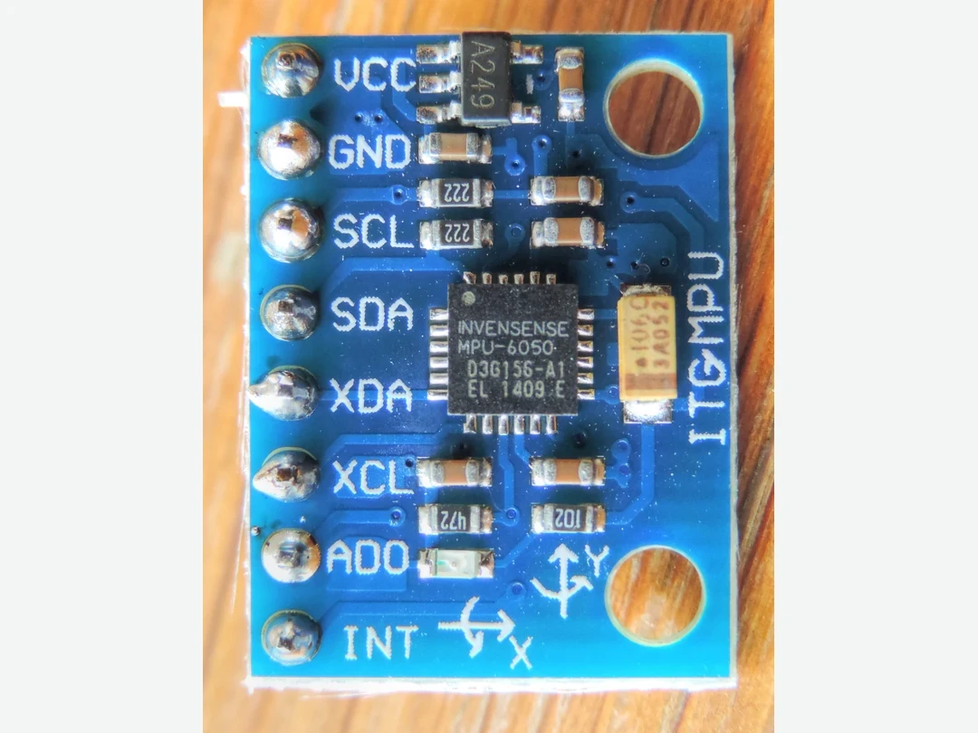
Measure the transform from IMU axes to the robot frame. Printed board arrows, chip axes and enclosure axes may differ. Verify signs with known single-axis motion before fusion.
Estimate bias online only when it is observable
A filter can include gyro and accelerometer bias as states. Those states become observable through motion and independent constraints such as gravity, zero velocity, visual features, lidar alignment or known contacts. Weak excitation can let bias trade against velocity, scale or gravity direction.
Monitor estimator covariance and residuals rather than assuming online estimation always converges. Use the rosbag2 recording workflow to preserve raw inputs for replay and fault analysis.
Validate drift, covariance and recovery on missions
Repeat cold start, warm start, stationary hold, known rotations, vibration, temperature, power cycling and representative trajectories. Compare against independent ground truth where available. Evaluate bias error, orientation drift, velocity and position error, innovation statistics and recovery after observation loss.
Release with a concise checklist.
- Define sensor axes, units and timestamp event.
- Calibrate offset, scale and cross-axis terms separately.
- Characterize temperature, noise and vibration.
- Verify online observability and covariance consistency.
- Repeat mission tests across reboot and environmental limits.
Frequently asked questions
Is subtracting a stationary zero enough to calibrate an IMU?
No. It estimates one bias condition but not scale, alignment, temperature, vibration or timing error.
Why does yaw drift while the robot is stationary?
A small gyro bias integrates into yaw, and gravity does not directly constrain heading.
Does Allan deviation correct every IMU error?
No. It characterizes stochastic behavior in stationary data; scale, alignment and dynamic effects need other tests.
Can accelerometer data be integrated twice for position?
Only briefly without strong constraints; bias, noise and orientation error make unconstrained position drift rapidly.
Does zero covariance mean the IMU is exact?
No. Zero may be interpreted incorrectly by consumers and does not prove uncertainty; publish a validated covariance model or the specified unknown marker.
Inertial Estimate and Validation Boundary
An IMU calibration is valid only for the identified sensor, configuration, mount and tested environment. Do not infer safety or navigation integrity from a low stationary drift alone.