Power and force limiting, or PFL, is a collaborative operating method in which contact consequences are restricted by application design and verified measurement. A robot marketed as collaborative does not establish acceptable contact after a tool, workpiece, path, fixture and person are added.
Testing begins with foreseeable contact scenarios. The engineer distinguishes transient impacts from quasi-static trapping, identifies body regions and directions, reproduces the installed robot configuration and records complete force and pressure behavior over time.
This guide is educational and does not replace the applicable standard, law or qualified machinery-safety assessment. Use it with the collaborative-robot safety guide and force-torque sensor guide.
Define PFL at the application level
PFL is not a property of the arm alone. The risk assessment covers the complete moving geometry, task, accessible contact points, expected people, workpiece, surrounding surfaces and every operating mode in which contact may occur.
Document which contacts are permitted, which must be prevented and which assumptions support the decision. A controller setting without this scenario boundary has no defensible acceptance meaning.

Separate transient and quasi-static contact
Transient contact allows separation after impact, while quasi-static contact can trap or clamp a body part between moving and fixed structures. The same peak-force number does not represent the same duration, pressure or escape condition.
Classify each scenario from physical geometry and motion. Test trapping between robot, tool, workpiece and fixture even when the arm surface itself is rounded.
| Scenario field | Record | Why it matters | Typical control |
|---|---|---|---|
| Contact type | Transient or trapped | Changes consequence | Spacing or force control |
| Body region | Foreseeable location | Different vulnerability | Prevent or limit |
| Geometry | Radius and area | Changes pressure | Round or pad |
| Motion | Direction and speed | Changes energy | Reduce speed |
| Configuration | Pose, load and tool | Changes effective dynamics | Recipe lock |
Build a contact-scenario matrix
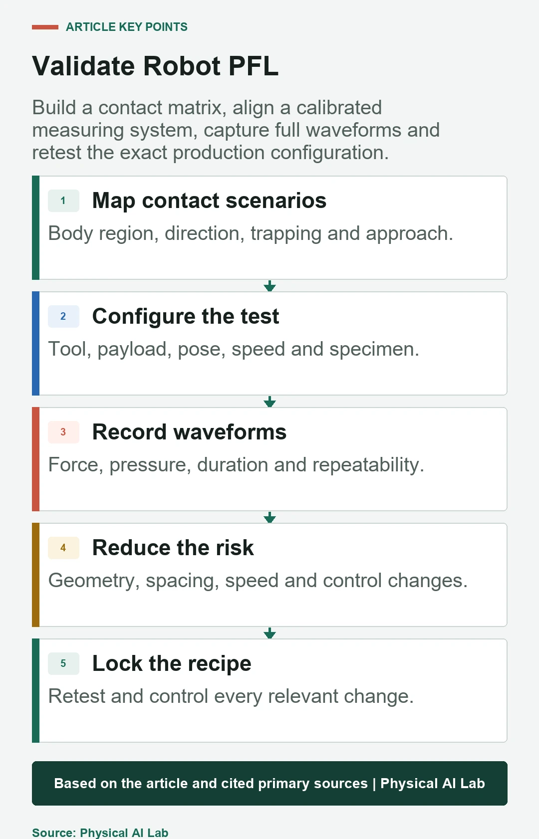
Use rows for contact point, body region, approach direction, trapping condition, robot pose, speed, payload, tool state and production mode. Include setup, recovery and maintenance where people may be closer than during normal cycles.
Prioritize credible worst cases but preserve rationale for excluded combinations. A single convenient test point cannot represent a changing multi-link robot application.
Measure force and pressure as different quantities
Force integrates load across the contact, while pressure depends on distribution over area. A narrow tool edge can create harmful local pressure even when total force appears modest.
Capture peak, duration, impulse where required, contact area or pressure response and repeatability. Keep the complete waveform so filtering or sampling does not hide a short peak.
Account for effective mass and robot pose
Contact energy depends on speed and the effective mass along the impact direction. Effective behavior changes with robot configuration, direction, payload, center of gravity and drive control, so one arm mass value is insufficient.
Test poses and directions that maximize credible response at each hazard point. Confirm programmed limits remain active in every production recipe.
Include tool and workpiece geometry
Sharp, pointed, hot, powered or abrasive tools can create hazards outside a simple force limit. A retained workpiece can add edges and inertia; a dropped workpiece creates a separate impact hazard.
Reduce risk through inherently safer geometry, guarding, separation or process changes before relying on contact limitation. PFL cannot make every process suitable for human proximity.
Do not substitute internal collision detection
Robot joint torque or motor-current monitoring can trigger a stop, but its signal is not the same as external contact force or pressure at the body. Sensitivity varies with pose, friction, payload and acceleration.
Use internal detection as part of the control strategy and validate it with independent application measurements. Include missed contact, nuisance trip and stopping response.
Use calibrated and repeatable test equipment
The measuring system needs an appropriate range, dynamics, sampling rate, contact surface and calibration traceability. Align it with the actual motion and constrain it to represent the modeled body contact condition.
Run repeats and record uncertainty. Reject setups that bottom out, saturate, slip or introduce support conditions unrelated to the scenario.
Apply current standards within scope
The official ISO catalog lists ISO/TS 15066:2016 as published guidance for collaborative robots and lists ISO 10218-2:2025 for industrial robot applications and cells.
Determine the applicable edition, jurisdiction, transition rules, measurement method and acceptance criteria with competent safety professionals. Public summaries do not replace the normative text.
Reduce risk and reproduce the same test
Possible controls include eliminating access, increasing clearance, rounding geometry, padding, lowering speed, changing path, reducing effective mass, modifying tools or adding protective functions. Select controls from the hazard hierarchy, not solely production convenience.
After a change, repeat the same documented adverse scenario so the improvement is comparable. Verify the modification did not create a new pinch point or longer exposure.
Lock PFL settings to production configuration
Tool, fingers, workpiece, payload, path, speed, acceleration, collision sensitivity and software versions define an approved configuration. Recipe selection and tool identification should prevent an untested combination from running in collaborative mode.
Revalidate after relevant changes and monitor drift, wear and brake or control behavior. Use the grasp-stability guide for retained-workpiece assumptions.
| Verification | Measure | Warning | Response |
|---|---|---|---|
| Geometry | Accessible points | New pinch | Redesign |
| Dynamics | Pose and speed | Worst case omitted | Expand matrix |
| Contact | Force and pressure | Waveform exceeds rule | Reduce risk |
| Control | Detection and stop | Pose dependence | Retune and retest |
| Change | Recipe identity | Untested combination | Block release |
Release a PFL validation file
Preserve risk scenarios, body-region rationale, installed configuration, test equipment and calibration, raw waveforms, uncertainty, acceptance criteria, risk-reduction actions, residual risk and change triggers.
Close review with the following checks.
- Classify transient and quasi-static contacts.
- Test the actual tool, workpiece, pose and speed.
- Measure force and pressure waveforms independently.
- Reduce non-contact process hazards separately.
- Lock approved configurations and retest every relevant change.
Frequently asked questions
Can a collaborative robot operate beside people without PFL testing?
Not on the product label alone; the complete application needs risk assessment and validation.
Does lowering the robot force limit always make contact safe?
No. Geometry, pressure, trapping, effective mass and stopping behavior also matter.
Is wrist force-torque data sufficient?
No. It can support diagnosis but does not replace calibrated contact measurement at the hazard point.
Are tests performed on people?
No. Use appropriate measurement equipment and the applicable validated method, not human subjects.
Does changing only the tool require reassessment?
Yes when geometry, mass, inertia, process energy, retention or reachable contact changes.
Measured-Contact and Application Boundary
PFL is an application-specific contact-risk control. Accept it only from scenario-based measurement, risk reduction, configuration control and competent validation under applicable requirements.