Emergency stop and protective stop can both halt robot motion, but they serve different purposes. Emergency stop is a complementary protective measure initiated for an emergency, while protective stop responds to a safeguarding or safety-related condition defined by the application.
Safe stop is often a family or vendor term rather than one universal final state. Engineers must read project and drive documentation and specify controlled deceleration, torque or brake state, residual energy, reset and deliberate restart for each hazard.
This guide is educational and does not replace standards, legal requirements or competent validation. Use it with the robot brake and safe-stop guide and SSM guide.
Define the purpose before the stop name
Write the hazard, initiating event, affected motion and expected risk reduction. A stop requested by a guard or scanner is not automatically equivalent to an emergency initiated by a person.
Document availability in every mode, including setup and recovery. A production stop used for convenience may lack the safety-related architecture and fault response needed for protection.

Specify the entire stop state transition
Describe request detection, communication, controlled deceleration if used, torque state, brake engagement, process-energy behavior, final monitoring and restart conditions. The word stopped covers many physically different states.
Include what happens after power loss and communication failure. Verify that the sequence does not create a drop, loss of balance or uncontrolled axis.
| Function term | Typical purpose | Initiator | Engineering question |
|---|---|---|---|
| Emergency stop | Respond to emergency | Human actuator | Does it reduce risk |
| Protective stop | Safeguarding condition | Safety device or logic | What condition clears |
| Operational stop | Process control | Automation | Is it safety related |
| STO | Prevent torque production | Safety drive function | What stops motion |
| Safe stop term | Project-specific sequence | Defined interface | Which exact function |
Do not infer behavior from a pushbutton
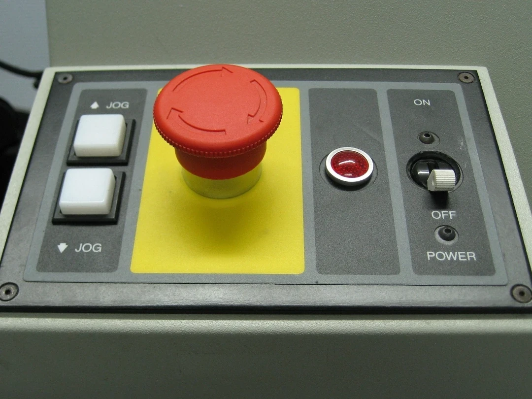
The red mushroom actuator is only one input. Protection depends on contacts or electronics, wiring, safety logic, communications, drives, brakes, actuators and the physical state of the machine.
Test accessibility, identification, latching, reset and the complete response. A working indicator lamp is not evidence of a verified safety chain.
Choose deceleration and final energy state from risk
Immediate torque removal can lengthen coast or release a gravity axis, while controlled stopping can rely on active control before a safe torque state. The correct sequence depends on dynamics, hazards and validated drive functions.
Specify what maintains a payload and what happens if controlled deceleration fails. Do not assume one category or drive acronym fits every axis and process.
Treat STO as torque prevention, not instant stopping
Safe torque off prevents torque-producing energy at the drive according to its defined function, but existing motion may coast and gravity or external forces may move the mechanism. Brakes or other measures can still be necessary.
Measure the achieved stop and residual motion for the application. Read the exact drive manual and validated architecture rather than expanding an acronym into an assumed physical outcome.
Control protective-stop reset and restart
Clearing a scanner or closing a guard does not prove the safeguarded area is empty or the task state is safe. Define reset location, visibility, presence detection and anti-repeat behavior.
Reset must not itself initiate hazardous motion. Require a separate deliberate start where the applicable risk assessment and standard demand it.
Control emergency-stop release and restart
Releasing an emergency-stop actuator only makes restart possible; it should not command motion. Investigate and clear the emergency, restore a safe state and use the defined restart procedure.
Prevent remote or automatic restart that surprises a person at the machine. Preserve event history and affected safety channels for diagnosis.
Measure adverse stopping time and distance
Test the most unfavorable relevant speed, direction, pose, payload, tool extension, temperature and brake condition. Measure from initiating condition to the defined final safe state, not just controller acknowledgment.
Use repeated trials and high-resolution traces to capture variability. Feed the result into guarding and separation calculations and monitor drift.
Control residual and process energy after stopping
Stopped robot joints can still leave suspended loads, pneumatic pressure, springs, rotating tools, heat, vacuum, welding or cutting energy. Define how each is secured or isolated for the scenario.
Emergency stop is not a substitute for required energy isolation during service. Link stop response to the end-effector safety guide.
Use current standards within scope
The ISO catalog lists ISO 13850:2015 as the current published emergency-stop design edition while its review lifecycle continues. It lists ISO 10218-2:2025 for industrial robot applications and cells.
ISO 13849-1:2023 and the current validation edition may also be relevant to safety-related controls. Determine applicable editions and legal requirements with competent professionals; this summary is not a normative design.
Inject faults across the safety chain
Test open and short circuits where appropriate, stuck contacts, sensor disagreement, communication loss, drive fault, brake failure, stale state and power interruption. Confirm detection, diagnostic response and achieved physical state.
A fault test should not stop at an error code. Observe motion, payload, process energy and restart inhibition.
| Test | Adverse condition | Expected evidence | Failure |
|---|---|---|---|
| Request | Input channel fault | Defined response | No detection |
| Deceleration | Worst load | Measured stop | Boundary exceeded |
| Energy | Power or pressure loss | Stable state | Drop or coast |
| Reset | Person remains exposed | Restart inhibited | Unexpected motion |
| Recovery | Multiple faults | Safe escalation | Silent bypass |
Release a stop-function specification
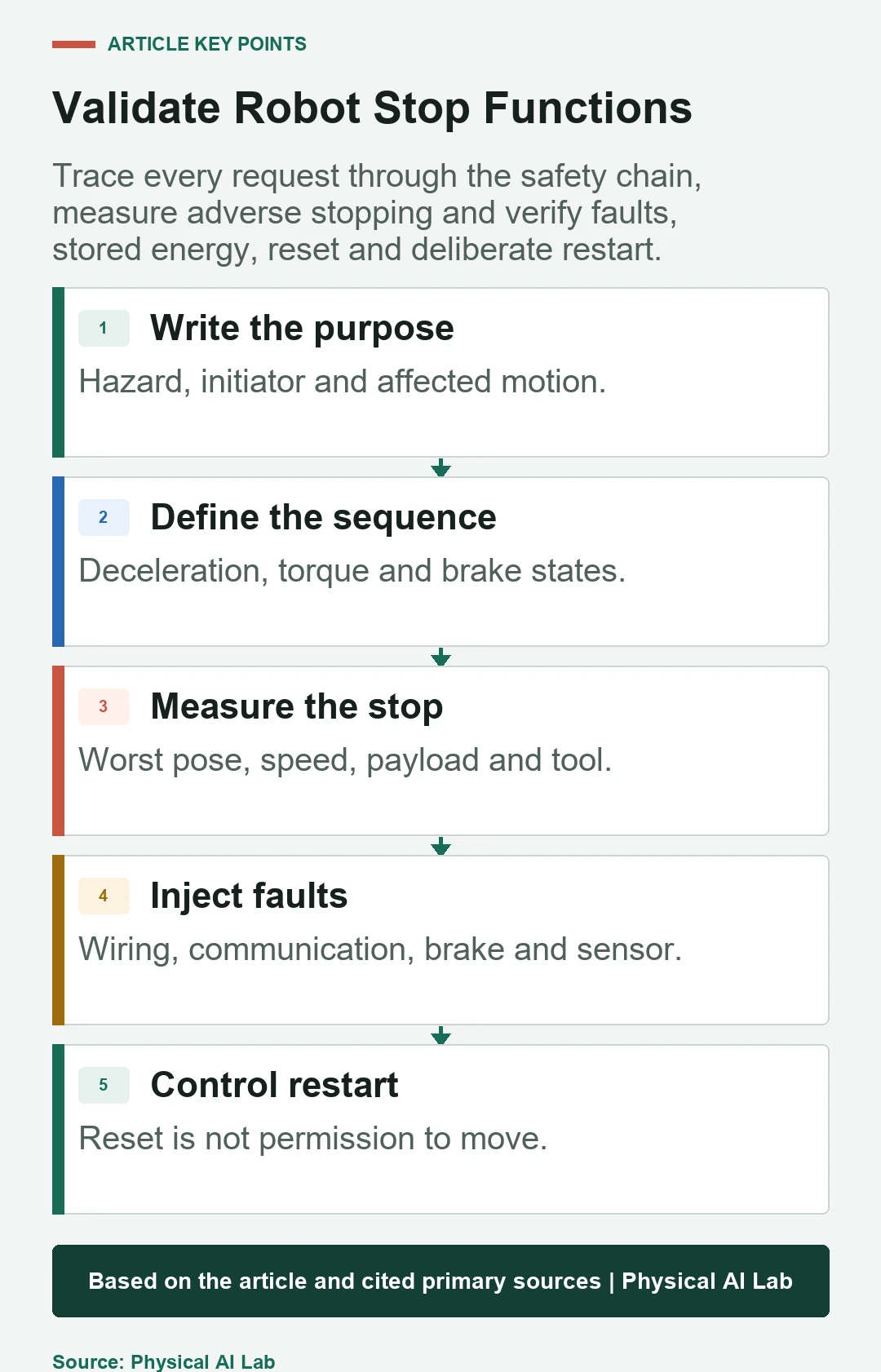
For every stop, record purpose, initiating devices, modes, affected hazards, sequence, drive and brake states, residual energy, required performance, measured stopping, faults, reset, restart, inspection and change triggers.
Close review with the following checks.
- Distinguish emergency, protective and operational purposes.
- Specify deceleration and the final physical state.
- Measure worst-case stopping and residual hazards.
- Inject faults through the complete safety chain.
- Keep reset separate from deliberate restart and from energy isolation.
Frequently asked questions
Does emergency stop remove all power?
Not necessarily; the design selects the risk-reducing stop and energy behavior for the machine.
Is protective stop the same as process stop?
No. A protective stop is part of a safeguarding response; a process stop may not be safety related.
May motion restart when an emergency-stop actuator is released?
No. Release enables a separate controlled restart after the emergency is cleared.
Does STO stop the robot instantly?
No. It prevents torque production; motion can coast or move under gravity unless other measures act.
Does emergency stop replace energy isolation?
No. Maintenance can require separate isolation, stored-energy dissipation and restart prevention.
Stop-Purpose and Restart Boundary
A robot stop function is a verified hazard-response sequence, not a label or button. Define the request, physical stop, energy state, faults, reset and deliberate restart for each application.