Robot predictive maintenance uses condition evidence to recognize degradation early enough to change a maintenance decision. It is not a promise that one vibration, current or temperature threshold can name every impending joint failure.
A useful program begins with failure modes and measurement physics, then controls sensor installation, operating context, time synchronization, data quality, alert cost and maintenance feedback. Without confirmed outcomes, an anomaly score cannot mature into a reliable diagnostic or prognosis.
Use this guide with the robot joint actuator testing guide and the robot joint thermal guide. Maintenance decisions remain subject to manufacturer instructions and qualified inspection.
Start from failure modes and actionable lead time
List bearings, gears, brakes, couplings, cables, cooling paths, encoders, lubricants and power electronics with their credible degradation mechanisms. For each one, state which physical signal could change, how early it must change and what maintenance action is possible.
Do not collect every available channel without a decision model. An alarm that appears minutes before seizure may protect equipment but cannot schedule a planned service visit; an early but nonspecific alarm can create excessive inspection cost.
Build a condition-monitoring program, not a sensor project
The official ISO catalog confirms ISO 17359:2018 as the current general guideline for setting up a machine condition-monitoring program. The process includes objectives, equipment and failure analysis, measurement methods, data handling, assessment and review.
Define owners for acquisition, diagnosis, maintenance decision, inspection feedback and model change. Keep safety-critical inspection intervals in force until evidence and the applicable approval process justify a change.

Control sensor mounting and operating context
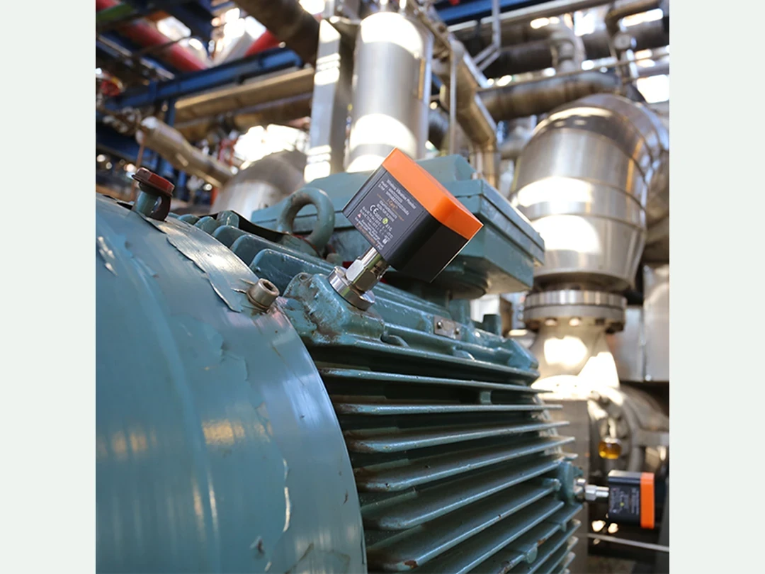
Vibration amplitude and spectrum change with mounting stiffness, location, direction, cable routing and sampling. Motor current changes with torque, speed and controller behavior; temperature changes with ambient conditions, duty cycle, cooling and sensor thermal lag.
Record pose, direction, speed, acceleration, payload, tool, task segment, ambient temperature, controller mode and software version. Compare like with like or normalize with a validated model.
Use vibration to observe mechanical dynamics
Time waveforms, spectra, order tracking, envelope analysis and trend features can expose imbalance, looseness, impacts, bearing or gear-related behavior under suitable conditions. Feature choice must follow the expected fault and the speed regime.
The official catalog says ISO 20816-1:2016 remains published but is expected to be replaced; it provides general vibration measurement and evaluation conditions rather than robot-joint acceptance limits. Use the applicable machine-specific guidance and validated baseline.
Use motor current as a load-sensitive observation
Current can reveal friction, torque ripple, binding or changing load, but the signal is shaped by current-loop dynamics, torque constant, field weakening, saturation, gravity compensation and the commanded trajectory. A current rise is not automatically a mechanical fault.
Compare requested current, measured phase or q-axis current, speed, acceleration and an independent torque or task reference. The motor-current torque-estimation guide explains calibration and residual checks.
Use temperature as a slow state with hidden internal gradients
Housing, winding, power semiconductor, bearing and lubricant temperatures are not interchangeable. Sensor placement and thermal time constants can cause a surface measurement to remain moderate while an internal hotspot approaches a limit.
Align temperature with accumulated load and cooling state. Controller derating can flatten the temperature trend while cycle time and current limit events worsen, so preserve control actions and production behavior beside the thermal signal.
Synchronize and qualify all evidence
Use a traceable time source or measured offsets so vibration windows, current transients, temperatures, controller faults and task events refer to the same physical episode. Record missing samples, clipping, aliasing, resampling and clock uncertainty.
Freeze feature code, units, filters and calibration. A dashboard trend reconstructed with a changed window or sensor gain is not comparable to the historical baseline unless the transformation is versioned and tested.
| Signal | Context to hold | Useful evidence | Major confounder |
|---|---|---|---|
| Vibration | Mount, speed and direction | Spectrum and impacts | Loose sensor or aliasing |
| Current | Command, speed and load | Torque-related residual | Controller compensation |
| Temperature | Ambient, duty and cooling | Thermal margin trend | Sensor lag and derating |
| Task result | Product and policy | Functional degradation | Scene difficulty |
| Inspection | Part and finding | Fault confirmation | Unstructured service note |
Fuse signals only when each contributes independent evidence
A gearbox problem may increase vibration, current residual and temperature, but correlated channels can also share one load change. Evaluate whether fusion improves detection, classification or lead time on held-out machines and operating regimes.
Keep individual signals available for diagnosis. A single opaque health score can hide a failed sensor, a changed task mix or disagreement that should reduce confidence rather than average away.
Set thresholds from risk, cost and validated performance
Define warning, inspection, controlled shutdown and immediate protection states separately. Evaluate false alarms, missed detections, lead-time distribution and the cost of unnecessary maintenance, not merely classification accuracy.
Use hysteresis, persistence and context-specific limits where justified. Protect safety independently: a predictive model is not a substitute for validated protective monitoring or manufacturer service limits.
Treat remaining-life estimates as conditional forecasts
A remaining useful life estimate depends on the present health state, future load profile, environment and failure definition. Provide an interval and the assumptions that generated it instead of one exact countdown.
The current third edition ISO 13381-1:2025 gives guidance and requirements for prognostics processes. Validate calibration, update behavior and decision usefulness on representative run-to-event or inspection evidence.
Close the loop with maintenance findings
When a joint is inspected or replaced, capture the suspected cause, measured wear, photographs or test results, part serial and the pre- and post-service signal. A returned-to-normal baseline is valuable counterevidence; no fault found is also a labeled outcome.
Feed outcomes into threshold and model revision under version control. The failure-mining workflow can prioritize uncertain or rare cases without overwriting the independent maintenance record.
Release a validated monitoring and maintenance file
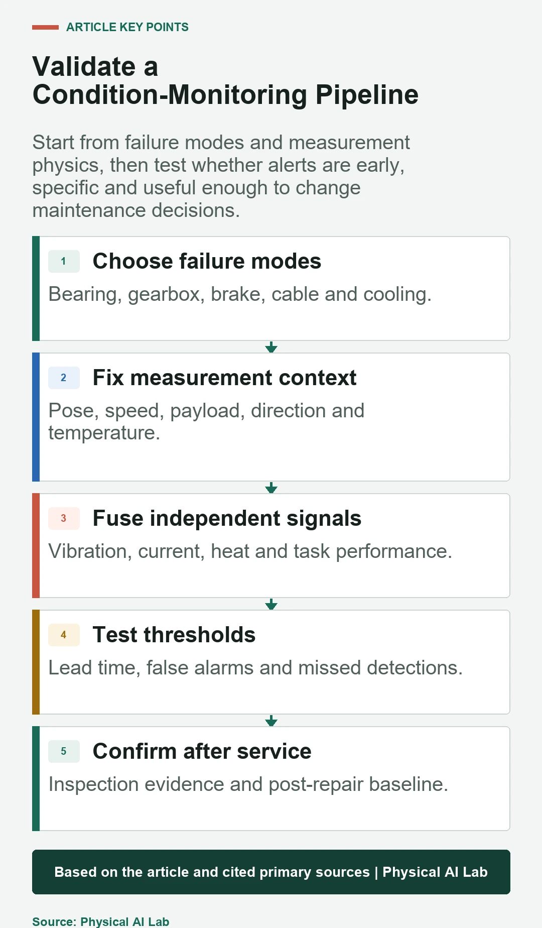
Preserve failure hypotheses, sensor location and calibration, operating context, acquisition and feature versions, baselines, thresholds, detection and prognosis performance, alert decisions, inspection findings and post-change verification.
Close review with the following checks.
| Acceptance gate | Required test | Decision evidence | Reject when |
|---|---|---|---|
| Acquisition | Repeatability and range | Known input response | Clipping or time error |
| Baseline | Representative regimes | Stable context bands | Task mix dominates |
| Detection | Held-out faults and normals | Miss and false-alarm rates | Only training fit |
| Prognosis | Calibration over horizon | Intervals and lead time | Exact unsupported date |
| Operations | Closed service loop | Action and confirmed finding | Alerts never adjudicated |
- Connect every monitored feature to a credible failure mode.
- Control mounting, time, operating state and data quality.
- Evaluate false alarms, misses and useful lead time.
- Keep protection independent of predictive models.
- Use service findings to confirm or reject every alert.
Frequently asked questions
Can one vibration threshold cover every robot task?
Usually not. Speed, pose, payload, mounting and task dynamics can change the baseline materially.
Does higher motor current prove gearbox wear?
No. It can also reflect load, acceleration, compensation, voltage or controller changes; use synchronized context and independent evidence.
Is housing temperature enough to protect a winding?
Not automatically. Internal gradients and sensor lag require a validated thermal relationship and manufacturer limits.
Can predictive maintenance replace scheduled safety inspections?
Not without the applicable engineering, legal and approval basis. Maintain required inspections while validating the monitoring program.
What should happen after a false alarm?
Preserve the evidence, identify the confounder, update labels and thresholds under change control, and verify that sensitivity to real faults remains.
Condition-Monitoring Evidence Boundary
Predictive maintenance earns trust through repeatable acquisition, operating-context control, confirmed failures and calibrated decision performance. An unverified anomaly score is a lead for investigation, not a maintenance fact.