Software-in-the-loop, or SIL, executes production or representative software against simulated components. Hardware-in-the-loop, or HIL, introduces real hardware into a closed test loop while the rest of the plant, sensors or environment remains simulated. The useful distinction is the boundary of reality, not the simulator product name.
SIL supports fast, deterministic scenario exploration. HIL exposes controller scheduling, real I/O, converters, networks and electrical behavior. Physical robot testing still reveals structural compliance, friction, installation, sensing and environmental effects that neither layer perfectly models.
Use this guide with the virtual commissioning guide and robot latency-budget guide. High-energy and safety-relevant testing requires controlled facilities and qualified personnel.
Define the real and simulated boundary for every test
List the real application code, controller CPU, I/O modules, networks, drives, sensors, plant dynamics, environment and operator interfaces. Identify whether each is production hardware, an emulator, a model, a replay or a test double.
State what the test cannot expose. A real controller connected only through an idealized software API may exercise scheduling but miss analog scaling, wiring faults and fieldbus timing; calling it HIL does not repair that gap.
Use SIL for fast and reproducible state-space exploration
SIL can run deterministically, faster or slower than wall clock, fork exact initial states and sweep thousands of environment, parameter and policy combinations. It is well suited to logic, state-machine, planner, perception and regression testing before hardware access.
Keep random seeds, simulator and asset versions, numerical settings and scenario definitions. A high simulated pass rate is evidence only for the modeled conditions and acceptance signals.
Use HIL to expose controller and interface behavior
HIL connects real control hardware to simulated inputs and plant responses at the production interface. It can reveal deadline misses, quantization, I/O scaling, bus timing, startup sequencing, watchdog behavior and recovery from link or power disturbances.
Verify electrical levels, sampling, transport, conversion and command application. If a bypass test port skips the production protocol or firmware path, record that difference and retain a separate interface test.
Treat a physical testbed as another controlled evidence layer
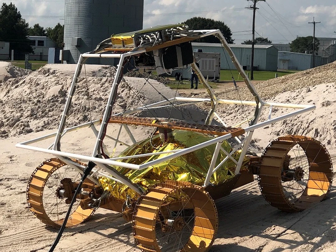
NIST describes its Manufacturing Robotics Testbed as combining representative robots, sensors, AGVs, measurement systems and simulations, including research on simulation validation. This illustrates why real and virtual components can be combined deliberately.
A physical testbed can measure motion, loads, perception and environmental interaction, but it still has limits in terrain, production variation and rare hazards. Document its differences from the deployed robot and site.

Translate one requirement into layer-specific observations
A requirement such as rejecting stale perception might be checked in SIL through timestamped scenarios, in HIL through real clock and bus behavior, and on the robot through measured sensor-to-motion response. The requirement remains the same while available measurements change.
Assign requirement ID, scenario, input, expected state, tolerance and evidence path at every layer. Do not let each test team invent an unrelated pass definition.
| Layer | Real elements | Primary evidence | Uncovered risk |
|---|---|---|---|
| SIL | Target software | Logic and scenario response | Hardware timing and physics |
| HIL | Controller and I/O | Deadlines and interfaces | Complete mechanics and site |
| Testbed | Robot or subsystem | Measured physical response | Production diversity |
| Site trial | Installed system | End-to-end operation | Rare long-term conditions |
| Fleet monitoring | Field population | Drift and recurrence | Controlled causality |
Express model fidelity as decision-relevant error
Avoid labeling a model simply high fidelity. Measure residuals that could change the test decision: stopping distance, contact force, actuator saturation, sensor noise, localization drift, energy use or latency under the scenario.
Define a validity domain for speed, load, pose, surface, lighting, temperature and fault type. Outside that domain, downgrade confidence or require another test layer.
Separate simulation time from real-time execution
A simulator step can advance regardless of how long computation takes, while a real controller must meet wall-clock periods and device deadlines. Faster-than-real-time SIL is valuable for coverage but cannot prove real-time feasibility.
In HIL, measure input arrival, controller release, computation, output transmission and plant-model response on qualified clocks. Use the robot time-synchronization guide when evidence crosses clock domains.
Inject faults at a controlled location and time
Specify whether a fault is introduced at sensor physics, digitization, message transport, controller memory, actuator command, power or mechanical plant. Record onset, duration, magnitude, correlation between channels and recovery or latching behavior.
A sensor value forced to zero does not represent every open wire, stale sample or plausible biased measurement. Use the failure analysis to choose injection points and preserve an independent safety envelope for hazardous cases.
Qualify the test rig and its own failure modes
Calibrate I/O, timing, loads and reference measurements. Verify that the simulator and interface hardware can create the demanded rates and extremes without saturating or silently dropping data.
Monitor test-rig health separately from the device under test. A rig overrun, stale plant model or failed channel should invalidate the run instead of appearing as a robot failure or pass.
Include diagnostics and safe failure in acceptance
Acceptance should cover not only command accuracy but detection, fault reporting, safe-state transition, restart control and evidence completeness. A system that reaches the expected output while hiding an injected fault may be unfit for operations.
Use independent oracles where possible. Compare commanded and measured state, controller diagnostics, test-rig truth and physical references so one corrupted signal cannot judge itself.
Run tests at frequencies matched to change risk
Put fast deterministic SIL checks in continuous integration. Run HIL on scheduled infrastructure for controller, interface and timing changes, and reserve physical rigs for correlation, high-consequence behavior and changes that alter mechanical or environmental assumptions.
Maintain a change-to-test matrix. A model, driver, controller, calibration, payload or network update can require different layers, and a failed correlation result should reopen earlier simulator assumptions.
Release a simulation-to-physical validation file
Preserve requirements, loop boundaries, model versions and validity domains, rig calibration, timing configuration, injected faults, layer-specific results, residuals to physical tests, unresolved gaps and release rationale.
Close review with the following checks.
| Evidence gate | Required artifact | Failure pattern | Escalation |
|---|---|---|---|
| Boundary | Loop and interface map | HIL label without detail | Reclassify test |
| Model | Validity domain and residual | Unbounded fidelity claim | Physical correlation |
| Timing | Qualified clocks and traces | Step time called latency | Real-time HIL |
| Fault | Injection specification | Zero-value shortcut | Interface-specific test |
| Release | Cross-layer traceability | Pass rates without gaps | Targeted robot trial |
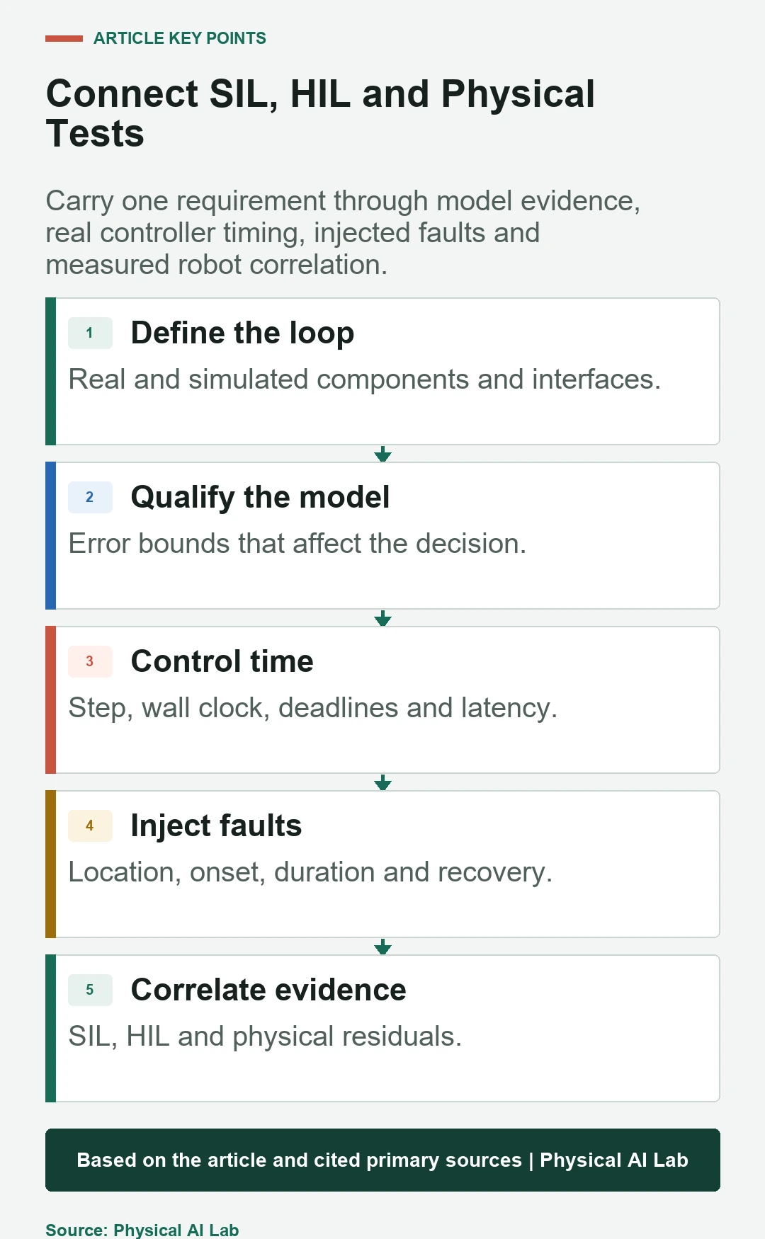
- Name every real, emulated, replayed and simulated component.
- Measure model error that can change acceptance.
- Separate simulated time from wall-clock deadlines.
- Inject faults at explicit interfaces with controlled recovery.
- Correlate SIL and HIL results against physical evidence.
Frequently asked questions
Does using a real controller make every simulator test HIL?
Only if the real hardware is in a defined closed loop at relevant production interfaces; document what remains bypassed.
Can a highly detailed SIL model eliminate physical tests?
No. It can reduce and focus them, but model validity must be established with physical evidence.
Which faults should be injected first?
Prioritize credible high-consequence failures, diagnostic gaps and changes that the current layer can inject safely and realistically.
Why separate simulation time and wall-clock time?
A correct simulated trajectory may take too long on real hardware, while a wall-clock deadline can fail even when model steps look correct.
How should SIL and HIL results be linked?
Use the same requirement and scenario IDs, layer-specific observations and measured residuals to physical behavior.
Simulation-to-Physical Evidence Boundary
SIL and HIL are evidence layers, not quality labels. Release only when the real-versus-simulated boundary, timing, fault model and correlation to the physical robot are explicit and decision-relevant.