A robot force and torque sensor measures interaction between a robot and its environment. A six-axis wrist sensor can report three force and three moment components as a wrench. Joint torque sensors, fingertip sensors and single-axis load cells observe different load paths and support different control objectives.
Useful contact measurement requires more than a sensitive transducer. The mechanical interface, range, overload protection, electronics, sampling, filtering, calibration, tool compensation and coordinate transforms all affect the signal used by the controller.
This guide links contact sensing to the robot actuator, position feedback and Physical AI control loop. Sensor ratings should be confirmed for the exact model and mounting.
Force sensors measure deformation in a designed load path
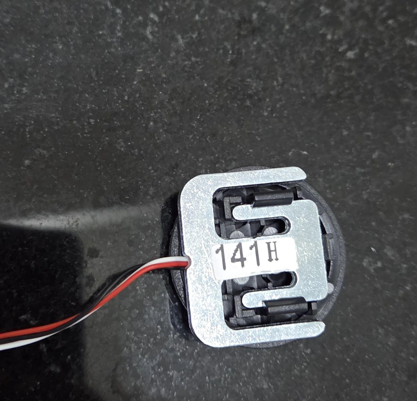
Many force sensors use strain gauges bonded to an elastic metal structure. Applied load creates small deformation, changing electrical resistance. A bridge circuit and electronics amplify and digitize that change. Other sensing methods use capacitive, optical or piezoelectric effects.
The mechanical structure is part of the measurement. Geometry sets sensitivity, stiffness, natural frequency and overload behavior. Mounting surfaces, bolts and adapters must transmit load as intended without introducing parasitic stress.

A six-axis sensor reports a wrench, not one force
The ATI selection guidance organizes multi-axis sensors by force, torque, size, stiffness and overload. Six measured channels are converted through a calibration matrix into forces and moments in the sensor coordinate frame.
Cross-axis sensitivity means a load in one direction can influence multiple raw channels. Calibration separates them within stated uncertainty. The controller must then transform the wrench to the tool, base or contact frame appropriate for the task.
Placement determines which loads are observable
A wrist sensor measures the combined load from the tool, payload, inertia and contact beyond the sensor. A joint torque sensor observes load through a particular joint structure. Fingertip sensing captures local contact but may not see the full object wrench.
Choose placement from the question the controller must answer. Is it detecting first contact, regulating polishing force, estimating payload, protecting a joint or balancing a humanoid? Loads that bypass the sensing element remain invisible.
| Placement | Observes | Strength | Blind spot |
|---|---|---|---|
| Robot wrist | Tool and external wrench | General manipulation feedback | Loads upstream of wrist |
| Joint torque | Load through one joint | Compliance and dynamics | Exact contact location |
| Fingertip | Local contact | Grasp and slip detail | Whole-arm load |
| Base or foot | Support reaction | Balance and contact | Local hand interaction |
Range and resolution must include predictable overloads
A smaller range can provide finer useful sensitivity, while a larger range accommodates payload and impact. Select force and torque axes separately because robot tasks can be highly asymmetric. Include tool weight, inertial loads and worst-case accidental contact.
Overload rating is not a normal operating target. Mechanical stops or guards can protect the transducer, but they may add alternate load paths or hysteresis. Test that overload protection preserves calibration and does not create unsafe structural failure.
Bias, drift and cross-talk require active management
Zero bias can change with mounting, temperature, cable forces and time. Cross-talk couples axes, and electronics add noise. A zeroing procedure should state robot pose, tool state, warm-up and whether external loads are present.
Monitor bias during operation without erasing real sustained forces. Temperature compensation should be validated over the intended range. Log raw and calibrated values when possible so unexplained behavior can be traced to sensing or transforms.
Tool weight and inertia must be removed correctly
A wrist sensor measures gravity on the tool and payload as well as contact. Compensation uses tool mass, center of mass, robot orientation and the coordinate transform from sensor to tool. Dynamic motion also produces inertial and Coriolis effects.
Incorrect payload or frame conventions can look like contact force. Calibrate tool properties with controlled poses and motions, and state whether the reported wrench is raw, gravity-compensated or dynamically compensated. Preserve the uncompensated signal for diagnostics.
Sampling and filtering create a control tradeoff
Filtering reduces high-frequency noise but adds phase lag. Force control near a stiff surface can become unstable when sensor delay, robot dynamics and controller gain interact. Mechanical resonance and structural compliance also shape the usable bandwidth.
Measure end-to-end latency from physical load to controller timestamp. Use anti-alias filtering and synchronized clocks. Select filter cutoff from the closed-loop task rather than visual smoothness in a plot.
| Measurement issue | Controller symptom | Diagnostic | Response |
|---|---|---|---|
| Bias drift | False steady contact | Unloaded trend versus temperature | Thermal model and zero policy |
| Cross-talk | Wrong directional response | Single-axis calibration load | Matrix and mounting review |
| Frame error | Force rotates incorrectly | Known load in several poses | Transform correction |
| Filter delay | Oscillation on contact | Frequency and latency test | Bandwidth and gain design |
| Overload | Offset or nonlinear output | Post-event reference check | Protection and recalibration |
Force control needs a stable inner motion system
Impedance control commands a relationship among motion, force and virtual stiffness. Admittance control converts measured force into motion. Hybrid approaches regulate selected force and position directions. Each depends on stable low-level joint control and correct frames.
Set contact approach speed, force limits, saturation and escape behavior. A noisy or saturated sensor should not command unlimited motion. Evaluate free-space, first contact, sliding, jamming and loss-of-contact transitions.
Calibration must cover the installed mechanical stack
Factory calibration describes the sensor under defined fixtures. Robot adapters, bolts, covers and cable routing can add stress or change thermal behavior. Verify zero, axis signs and scale after installation with known loads and moments.
Recheck after overload, tool collision, service or unusual drift. Calibration records should include serial number, fixture, orientation, temperature and uncertainty. A numerical matrix without traceability is not sufficient evidence.
Validation should reproduce real contact tasks and faults
Bench tests should apply known forces and moments across axes, range, temperature and frequency. Robot tests should cover the actual tool, payload, surface stiffness, speed and motion. Compare controller response with an independent reference where practical.
Inject disconnection, frozen data, saturation, timestamp delay and implausible jumps. Confirm the robot limits motion or enters the intended safe response. Track calibration drift and overload events across field operation.
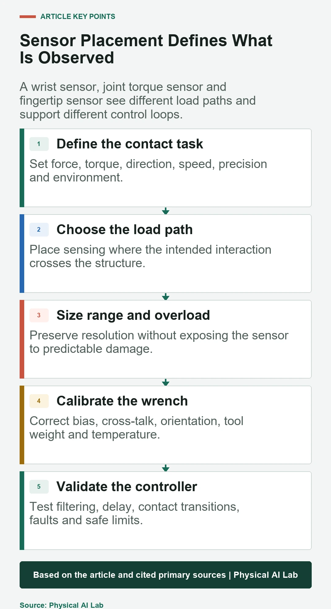
- Define the task and observable load path.
- Size operating range and overload protection.
- Calibrate bias, cross-talk and coordinate frames.
- Measure filtering and end-to-end latency.
- Validate contact transitions and sensor faults.
Frequently asked questions
What does a six-axis force torque sensor measure?
It reports three orthogonal force components and three moments in a defined sensor coordinate frame after applying a calibration matrix.
Where should a robot force sensor be installed?
Place it in the load path relevant to the task. Wrist, joint, fingertip and foot sensors observe different interactions.
Why must a force sensor be zeroed?
Mounting stress, temperature and electronics create bias. Zeroing establishes a reference, but the procedure must not remove a real sustained load.
Does more filtering improve force control?
Not automatically. Filtering reduces noise but adds delay and phase lag, which can destabilize contact control. Tune it with the complete loop.
Can motor current replace a force sensor?
Current can estimate motor torque, but friction, transmission behavior and model uncertainty reduce accuracy. Direct sensing is useful when the task requires verified contact feedback.
Contact Sensing Note
Force and torque ratings, overload limits and calibration uncertainty are model-specific. Verify current manufacturer documentation and validate the installed sensor, transforms and controller under representative contact and fault conditions.