A planetary gearset combines a sun gear, planet gears, ring gear and carrier. Ratio and rotation direction depend on which member is fixed, driven and used as output. Stating only “planetary reducer” is therefore incomplete.
Robot joints value planetary systems for coaxial packaging, torque sharing and good efficiency at modest ratios. Backlash, carrier deformation, unequal planet loading, stage accumulation and lubrication still determine precision and life.
This guide complements the quasi-direct-drive actuator guide and joint actuator testing. Verify tooth geometry and ratings with the selected manufacturer’s current method.
Define the sun, planets, ring and carrier
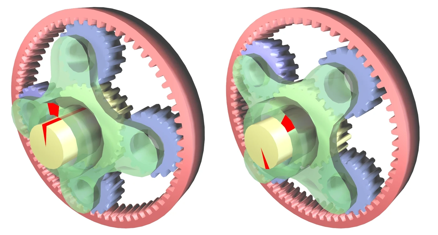
The central sun meshes with planets mounted on the carrier, and the planets mesh with the internal ring. Any member may serve as input, output or fixed reaction in a general epicyclic arrangement.
Draw arrows for all four members before calculating ratio. The same tooth counts produce different results if the ring is fixed instead of the carrier or if input and output swap. Include sign convention for rotation direction.

A fixed-ring reduction has a direct tooth-count relationship
A common robot arrangement fixes the ring, drives the sun and takes output from the carrier. The MathWorks planetary-gear reference shows how member constraints determine relative motion and ratio.
Confirm the exact definition used by the supplier, especially for compound planets or multiple stages. Ratio alone does not specify torque capacity, inertia, backlash or packaging.
| Member | Common fixed-ring role | Key design input | Typical error source |
|---|---|---|---|
| Sun | High-speed input | Tooth count and shaft support | Runout and mesh error |
| Planets | Load-sharing meshes | Count, phase and bearings | Unequal loading |
| Ring | Fixed reaction | Internal teeth and housing fit | Distortion |
| Carrier | Low-speed output | Pin and plate stiffness | Deflection |
| Second stage | Additional reduction | Interface and clocking | Accumulated error |
Multiple planets can share torque
Several planets create parallel load paths and support compact torque density. Equal sharing requires accurate tooth geometry, planet-pin location, carrier stiffness and compatible phasing. Adding planets does not guarantee proportional capacity.
Measure tooth contact and strain or infer load balance from temperature and wear when direct sensing is difficult. Carrier and ring deformation can bias one planet even when nominal spacing is equal.
Planet count and phase must satisfy assembly geometry
Sun, ring and planet tooth counts constrain whether equally spaced planets can mesh in phase. Assembly conditions become more complex with compound planets and staged reducers.
Validate geometry in the design tool and with a physical timing procedure. A set that can be forced together may still have phase error, interference or unequal load. Preserve gear clocking during service.
Single-stage reducers favor efficiency and backdrivability
One modest-ratio stage uses fewer meshes and bearings than a multistage reducer. It can provide higher efficiency, lower reflected inertia and easier backdrive, which is useful for torque control and compliant joints.
Low ratio requires a motor capable of higher torque. Evaluate the complete motor-reducer mass and electrical loss. A more efficient gearset can still create a hotter actuator if it moves the motor into an inefficient region.
Additional stages multiply ratio and imperfections
Two stages multiply their ratios but also add mesh loss, inertia, backlash, manufacturing variation and bearing support. Alignment between stages and carrier interfaces affects noise and life.
Allocate the error and torque budget by stage. The high-speed stage sees different cycles and lubrication than the output stage. Do not assume two reducers with the same total ratio have the same efficiency or reversal behavior.
| Property | One stage | Two or more stages | Robot implication |
|---|---|---|---|
| Ratio | Moderate | Higher | Motor operating point |
| Efficiency | Generally higher | More mesh losses | Battery and heat |
| Backlash | One contribution | Contributions accumulate | Reversal accuracy |
| Reflected inertia | Lower architecture burden | More rotating parts | Force response |
| Packaging | Larger gears for ratio | More axial or radial complexity | Joint envelope |
Backlash comes from more than tooth clearance
Tooth-side clearance prevents interference and allows lubrication, but carrier pin clearance, bearing play, ring distortion and stage interfaces also contribute. Preloaded or split arrangements can reduce reversal error at the cost of friction and complexity.
Measure lost motion under defined torque rather than reporting only unloaded angular play. Repeat around the output revolution and over temperature because local gear error and expansion change the result.
Carrier stiffness controls load sharing and output accuracy
Planet pins load the carrier plates, which bend and twist under torque. Carrier deformation changes planet alignment and output angle. A compact thin carrier can negate the theoretical benefit of multiple planets.
Analyze pin support, plate spacing, bearing arrangement and output interface together. Verify moment load from the robot link, not only pure torque. Inspect contact patterns after representative loading.
Lubrication and temperature affect low-speed behavior
Gear mesh, planet bearings and seals need lubricant compatible with speed, load, material and life. Viscosity affects churning at high speed and friction at low speed. Temperature changes clearances and preload.
Map efficiency, breakaway torque and ripple from cold start to steady state. Account for orientation and grease migration. Noise or current change can reveal degradation but needs a baseline and confirmed root cause.
Choose the reducer with the motor and control objective
Compare ratio, continuous and peak torque, motor speed, reflected inertia, efficiency, backdrivability, backlash, stiffness, thermal limits, mass and service. QDD favors lower ratios and backdrive, while position-dominant axes may accept higher ratios.
Test the assembled joint through real trajectories and reversals. Record output torque, angle, ripple, temperature and efficiency. The final design is a motor, gearset, sensing and control system, not an isolated ratio.
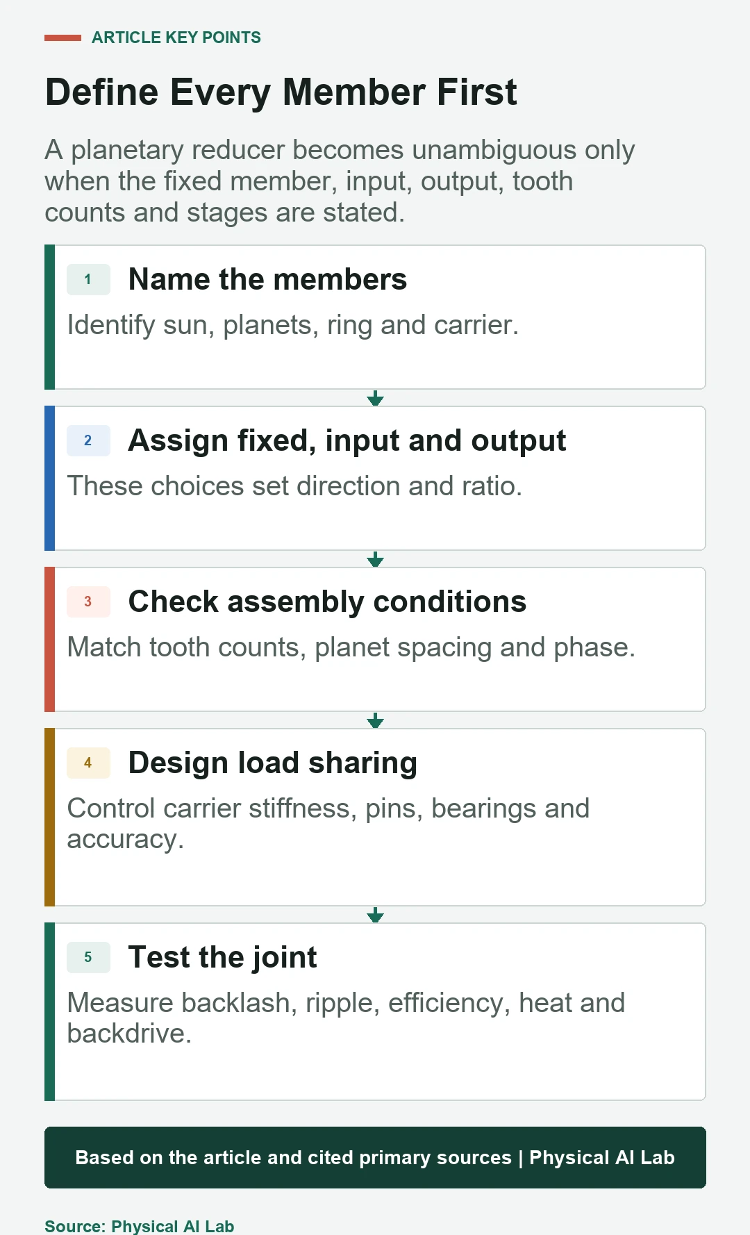
- Name fixed, input and output members.
- Validate tooth-count and planet-phase conditions.
- Design carrier stiffness for equal load sharing.
- Budget backlash and loss by stage.
- Measure output behavior across load and temperature.
Frequently asked questions
Why can planetary reducers have high torque density?
Multiple planet meshes create parallel load paths in a coaxial package when geometry and carrier stiffness share load well.
Are more planets always better?
No. Assembly phasing, carrier space, bearing size and unequal load can limit the benefit.
Does a single-stage planetary reducer have zero backlash?
No. Tooth clearance, bearings, carrier and housing still create reversal error.
Why are planetary reducers common in QDD actuators?
A modest ratio can preserve efficiency and backdrivability while multiplying motor torque in a compact joint.
Are one-stage and two-stage reducers equivalent at the same ratio?
No. Stage count changes efficiency, inertia, backlash, packaging, load distribution and thermal behavior.
Gearset Definition Note
Planetary gear geometry, allowable loads and assembly conditions are design specific. Verify tooth counts, phase, materials, lubrication and life with the manufacturer or qualified gear engineer, then test the assembled joint.