Robot actuator torque density expresses torque relative to mass or volume, but the number is meaningful only when torque location, duration, speed, temperature and hardware boundary are fixed. A motor’s peak torque divided by motor mass is not the same metric as continuous joint-output torque divided by the complete actuator mass.
Robot joints combine motor, transmission, bearings, output structure, encoder, brake, electronics, cabling and cooling. Each component changes usable torque and adds mass or volume. The best design depends on the robot’s duty cycle and link placement, not on the largest isolated newton-meter-per-kilogram value.
Use this guide with the joint actuator test guide and joint thermal guide. Published values should be treated as comparable only after their definitions and test conditions match.
Separate peak, continuous, mass-specific and volumetric torque
Peak torque is available for a limited duration before current, voltage, demagnetization, mechanical or thermal limits intervene. Continuous torque is sustainable at a stated ambient, cooling condition and allowable winding or case temperature. Divide either value by mass for specific torque or by occupied volume for volumetric torque density.
State whether torque is measured at the motor shaft or joint output. Also state the counted mass and envelope. A fair joint metric normally includes every component required to transmit, support, sense and control the output under the claimed operating condition.

Trace torque from motor current to joint output
Motor torque begins with electromagnetic torque generated from controlled current. The transmission multiplies torque approximately by reduction ratio and efficiency, while speed falls. Bearings, seals, gearing and cable forces consume part of the output and make efficiency dependent on speed, load, direction and temperature.
Current limit determines short-term motor torque; bus voltage and back electromotive force limit current at speed. A high static output value can collapse at operating speed. Plot the output torque-speed envelope rather than reporting one stall point.
| Metric | Numerator | Denominator | Required condition |
|---|---|---|---|
| Motor specific peak torque | Motor-shaft peak torque | Motor mass | Peak duration and current |
| Motor continuous torque density | Sustainable motor torque | Motor mass or volume | Ambient and cooling |
| Joint peak torque density | Output peak torque | Complete joint mass | Ratio, efficiency and duration |
| Joint continuous torque density | Sustainable output torque | Complete joint mass or volume | Thermal steady state |
| Task-effective density | Duty-cycle output torque | Installed actuator burden | Speed, pose and repetitions |
The motor is only one part of the installed mass
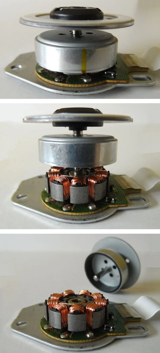
A frameless motor can integrate into the joint housing and share structure, but the design still needs a rotor hub, stator support, air gap, bearings, encoder, power conductors and thermal path. Integration may remove redundant housings or may add precision structure and assembly cost.
Use a mass budget with explicit boundaries. Include distributed electronics and cooling hardware when they exist only for that actuator. For moving links, also consider where the mass sits because distal mass increases whole-limb inertia more than the same mass near the base.
Reduction ratio cannot raise usable density without limit
Higher ratio multiplies motor torque, but the reducer must carry higher output load and may become heavier. Speed, efficiency, backlash, compliance, reflected inertia and backdrivability also change. Gear contact and bearings introduce their own continuous and peak limits.
Optimize the motor and ratio together against the output duty. A small fast motor with a large reducer can score well on static torque yet deliver poor contact transparency or dynamic power. A low-ratio actuator may need a larger motor but reduce transmission complexity.
Mass and volume metrics favor different packaging
Specific torque matters strongly for legged and humanoid links where moving mass affects energy and dynamics. Volumetric torque density matters when a shoulder, wrist or hand must fit a narrow envelope. A low-mass actuator with a large diameter can still be unusable in the target joint.
Record axial length, diameter, central bore, cable exits and service clearances. Compute mass and volume with the same installed boundary. A catalog motor’s active-stack volume should not be compared with a competitor’s complete housing envelope.

Continuous torque is a thermal-system result
Copper loss grows roughly with current squared, while iron, inverter, bearing and seal losses depend on speed and operating point. Heat must cross winding insulation, stator, housing and any coolant interface before reaching ambient. The allowable temperature is set by magnets, insulation, lubricant, sensors and nearby structures.
Specify ambient, airflow or liquid temperature, flow rate, mounting plate and warm-up state. Continuous torque measured on a large cold fixture is not portable to a sealed robot link. Use thermal steady state or a defined periodic duty model.
| Test | Primary output | Boundary to control | Typical misleading result |
|---|---|---|---|
| Stall torque | Static output torque | Current and duration | Peak reported as continuous |
| Torque-speed sweep | Output map and efficiency | Bus voltage and temperature | Low-speed point generalized |
| Thermal duty | Steady temperature and torque | Cooling and ambient | Cold-start advantage |
| Repeated peak | Temperature and derating | Pulse and recovery time | Single pulse extrapolated |
| Life exposure | Wear and drift | Load spectrum and cycles | New-unit density only |
Calculate joint density from one defined boundary
Begin with required output torque, speed and time history. Select candidate motor, ratio and drive, then estimate output torque after efficiency and current-voltage limits. Sum the mass of motor, reducer, bearings, housing, sensors, brake, drive and dedicated thermal hardware.
Compute separate peak and continuous values. Repeat across the speed and temperature map. Add a task metric such as root-mean-square torque over one cycle and check whether regenerative phases reduce bus energy without reducing mechanical or thermal stress.
Promising numbers can fail through integration details
A compact motor can overheat when bonded poorly to the housing. A light reducer can distort under moment load. Encoder placement can hide output compliance. Cable bends and seals can add friction that dominates small torque commands.
Review air gap, alignment, preload, lubrication, fasteners, connector volume and service access. Measure the assembled joint because integration errors can erase the component-level advantage. Record manufacturing variation across more than one unit.
Output testing needs torque, speed and temperature together
The Open Dynamic Robot Initiative actuator hardware shows how motor, belt reduction, encoders, bearings and structures form one torque-controlled module. Use comparable output-side tests rather than inferring the module from motor data.
Instrument input electrical power, motor and output position, output torque, key temperatures and controller limits on a synchronized clock. Test both directions, multiple speeds and thermal states. Report uncertainty and the exact hardware revision.
Choose density that survives the robot duty cycle
The winning actuator meets torque, speed, power, stiffness, backdrivability, thermal, life, noise, package and service requirements together. A lower peak density can be the better system if it delivers more continuous torque or needs less cooling and protection hardware.
Freeze definitions before ranking candidates. Recalculate after every material boundary change, then validate the installed joint in representative motion. Treat maximum torque as a time-limited operating state with explicit entry and exit conditions.
- Fix output location, mass boundary and volume boundary.
- Separate peak duration from continuous thermal operation.
- Include ratio, efficiency, speed and bus voltage.
- Count housing, bearings, sensing, brake and cooling.
- Verify the assembled output over the real duty cycle.
Frequently asked questions
Is the highest newton-meter-per-kilogram actuator always best?
No. Speed, duration, cooling, volume, stiffness, backdrivability, life and the counted hardware boundary can reverse the ranking.
Are continuous torque and rated torque identical?
Not automatically. Read the manufacturer’s definition, ambient, cooling, speed and allowable temperature.
Does a higher reduction ratio always improve torque density?
No. The reducer gains mass and losses while output speed, inertia, compliance and backdrivability change.
Should a humanoid prioritize mass or volume density?
Both can matter; distal moving mass affects dynamics, while joint diameter, length and routing constrain packaging.
How is torque density verified?
Measure output torque, speed and thermal state with a documented complete-joint mass or volume and duty cycle.
Performance Boundary Note
Torque-density claims are valid only within stated output, duration, speed, temperature, cooling and mass or volume boundaries. Recalculate and test the complete installed joint before using a component specification in robot-level decisions.