Peg-in-hole assembly converts position and orientation error into contact force and moment. A successful system controls approach energy, detects contact, searches within known geometry, recognizes insertion and seating, and leaves safely when the evidence is inconsistent.
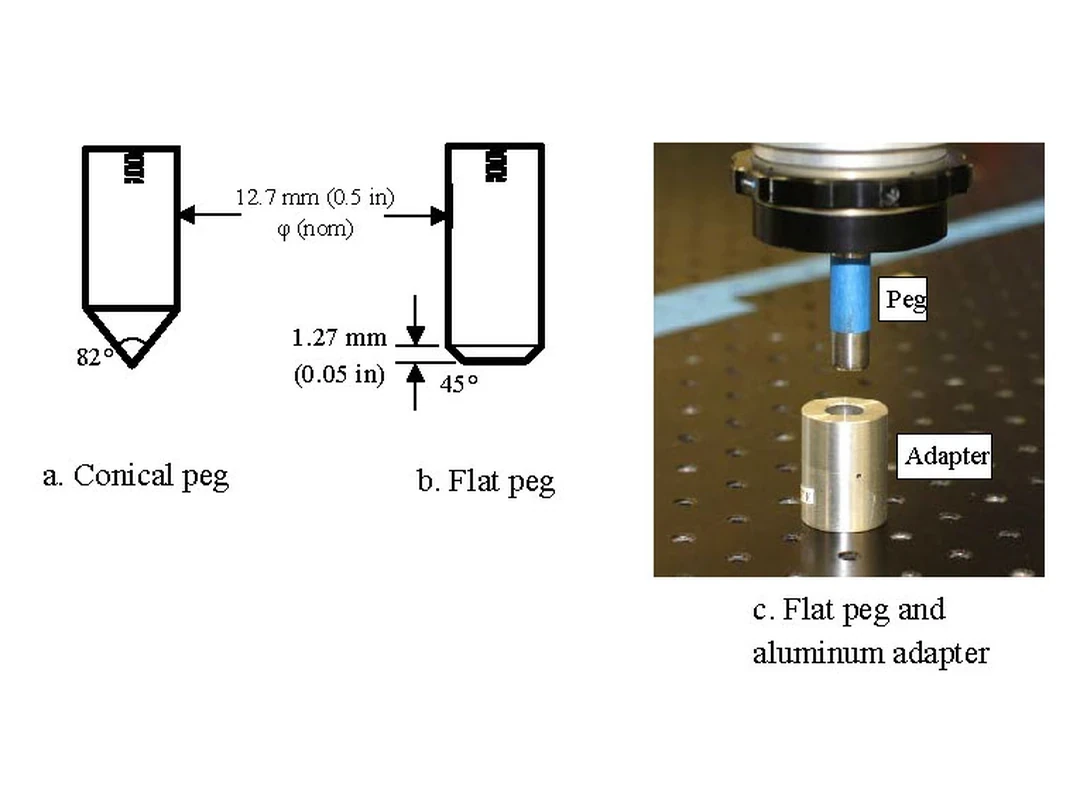
Tolerance, chamfer, peg tip, fixture compliance, surface finish and lubrication define the physical capture region before software begins. A search path that succeeds on a large chamfer may jam or damage a tight sharp-edged production part.
Use this guide with the robot force-torque sensor guide and impedance versus admittance guide. Validate every state and stop condition on the exact assembly.
Define the mechanical capture and damage envelope
Record peg and hole diameters, clearance, roundness, straightness, chamfer, lead-in, insertion depth, surface finish and fixture stiffness. Include tolerance stacks and thermal change. These parameters determine how much lateral and angular error contact can correct.
Define allowable axial force, lateral force, bending moment, surface pressure and cycle wear. The controller must remain inside both part and robot limits.
The NIST peg-in-hole data demonstrates why controlled peg geometries and test artifacts matter when comparing manipulation performance.
Calibrate the hole, tool and force frames
The insertion axis, peg datum, tool center point, force-sensor frame and fixture frame must be related through calibrated transforms. A small angular error creates edge contact that grows with insertion depth.
Verify transforms with held-out targets and the coordinate-frame workflow. Bias and gravity-compensate the force sensor in the current tool orientation.
| Mechanical variable | Control consequence | Measurement | Failure if unknown |
|---|---|---|---|
| Radial clearance | Search capture range | Gauge or metrology | Persistent edge contact |
| Chamfer and tip | Centering behavior | Drawing and inspection | Unexpected jam |
| Fixture stiffness | Force-displacement slope | Load test | False insertion cue |
| Insertion depth | Seat criterion | Position or datum | Early completion |
| Surface condition | Friction and wear | Process control | Cycle drift |
Approach in position with bounded energy
Free-space motion can use position control until a pre-contact region, but speed and effective inertia should fall before possible collision. Stopping distance and force-sensor delay belong in the approach budget.
Use a guarded move with maximum travel, time and force. If expected contact does not occur, stop and classify missing part, wrong pose or sensor failure rather than continuing indefinitely.
Detect contact from force, moment and persistence
Axial force alone can confuse cable load, gravity error and friction with contact. Combine axial and lateral force, bending moment, position error, velocity and duration. Use hysteresis to avoid toggling at noise level.
Timestamp force and motion signals with the robot timing workflow. A delayed force threshold can allow damaging travel before the state changes.
Switch to compliant behavior after contact
Continuing stiff position control after contact converts registration error into large load. Impedance control can lower selected Cartesian stiffness; admittance control can convert measured wrench into a motion correction around a position-controlled robot.
Choose axes intentionally. The insertion axis may regulate a small force while lateral axes search compliantly. Saturation, delay and frame errors can destabilize contact, so tune at reduced energy.
Bound spiral or raster search by geometry
A spiral, raster or learned search is a policy for exploring candidate center locations under contact, not proof that the hole lies within the path. Radius, pitch, speed, force and dwell determine both coverage and wear.
Limit search to the mechanically plausible capture region. Abort on excessive lateral force, moment, path length, time or repeated unproductive cycles.
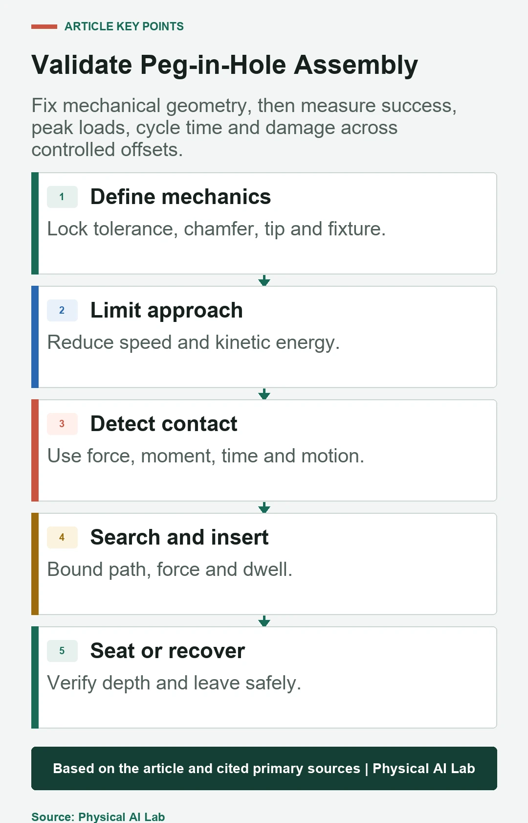
| State | Positive evidence | Stop condition | Next action |
|---|---|---|---|
| Approach | Expected path clear | Contact or travel limit | Contact or reject |
| Contact | Persistent bounded wrench | Impact or sensor fault | Compliant search |
| Search | Changing contact and feasible region | Force, time or radius limit | Insert or recover |
| Insertion | Depth increases with bounded lateral load | Wedging or no progress | Continue or retract |
| Seat | Depth and force pattern agree | Ambiguous completion | Accept or inspect |
Recognize insertion from multiple signals
Hole entry often produces increasing depth with a change in axial force and reduced lateral error or moment. One force drop can also result from lost contact or part motion. Combine depth progression, wrench pattern and expected geometry.
Require persistence over a short window and track uncertainty. Do not declare success while commanded motion advances but measured robot or part motion is stalled.
Distinguish jamming from wedging and normal friction
Jamming can occur when contact forces prevent insertion without necessarily exceeding static friction, while wedging involves frictional self-locking under geometry and load. Both appear as poor depth progress with characteristic lateral force and moment.
Use force direction, moment, depth derivative and commanded compliance to classify the event. Repeated pushing can increase damage and make recovery harder.
Verify seating with independent completion evidence
Final depth, end-stop force, flange contact, electrical continuity, vision or a downstream functional test can indicate seating. Select signals from the actual assembly; a depth threshold alone can accept a short or obstructed part.
Define allowed final force and relaxation behavior. Confirm that the part remains seated after the robot releases or changes load.
Design recovery as a normal state transition
Recovery may hold, reduce force, retract along the insertion axis, return to a safe pose, reacquire the part or request inspection. The path must avoid dragging a tilted peg across the hole edge.
Bound retry count and cumulative force, time and wear. A retry should change a diagnosed condition; repeating identical motion is not a recovery strategy.
Validate offsets, parts and lifecycle variation
Sweep lateral and angular error, clearance, chamfer, friction, part lot, sensor bias, payload, speed and fixture stiffness. Include worn tools, burrs, missing parts and misloaded fixtures. Measure success, peak wrench, energy, cycle time, damage and recovery rate.
NIST reports such as comparative peg-in-hole testing illustrate force-based performance evaluation. Use your production geometry and acceptance limits.
Operate with a traceable assembly state machine
Log state entry and exit, transforms, force bias, pose, wrench, thresholds, search path, progress, abort reason, retry and final inspection. Preserve raw synchronized signals for failure replay.
Release with a concise checklist.
- Control mechanical geometry and tolerances.
- Calibrate tool, hole and force frames.
- Bound approach, search and insertion energy.
- Use multi-signal entry, jam and seat evidence.
- Validate recovery, retries, wear and part variation.
Frequently asked questions
Is a camera sufficient for peg-in-hole assembly?
It can reduce initial error, but tight insertion usually benefits from contact evidence and compliant behavior.
Should spiral search radius be as large as possible?
No. It should cover the plausible error region while respecting part, force, time and collision limits.
Is one contact-force threshold enough?
Usually not. Direction, moment, duration, motion and sensor bias help distinguish contact from other loads.
How should insertion completion be verified?
Combine depth and wrench pattern with assembly-specific evidence such as seating contact, continuity or inspection.
How many retries are appropriate?
Set a bounded count from failure modes, damage risk and whether each retry changes a diagnosed condition.
Contact Search and Damage-Prevention Boundary
Force-controlled insertion can damage parts and robots. Commission at reduced energy with mechanical limits, qualified supervision and application-specific safety controls.