A vacuum gripper retains a part by creating a pressure difference across an effective sealed area. The useful holding force is not the catalog vacuum value alone. Cup geometry, leakage, surface condition, load direction, acceleration, center-of-mass offset and pad deformation all change the available margin.
A successful pickup is only the first state. The system must build vacuum within a deadline, keep the part through the complete trajectory, detect degradation before loss and release it at the intended place. These states require different thresholds and evidence.
Use this guide with the robot gripper selection guide and grasp stability guide. Validate the installed pump, valves, hoses, cups, part set and robot motion as one system.
Start with pressure difference and effective seal area
The ideal normal holding force is pressure difference multiplied by effective area. Real cups lose part of that result through seal geometry, lip deformation, leaks and uneven pressure. Use measured pressure at the tool, not only a pump rating taken at another flow condition.
Force direction matters. Normal separation, tangential sliding and peel at a cup edge are different failure modes. Gravity and robot acceleration must be resolved in the cup and part frames so the calculation follows the actual tool pose.

Classify rough, porous, curved and contaminated surfaces
Roughness creates small leak paths at the lip. Porous cardboard, foam or fabric can pass air through the material even when the rim contacts well. Curvature can reduce the sealed area, while oil, dust, labels and seams change friction and sealing over time.
Build a part-condition taxonomy and keep representative worst cases. A clean laboratory sample cannot stand in for a worn shipping box, molded texture, warped panel or oily production part.
| Surface condition | Primary failure | Useful evidence | Typical control response |
|---|---|---|---|
| Rough | Rim leakage | Pressure decay and lip imprint | Softer or larger cup |
| Porous | Through-flow | Pump flow and slow evacuation | Higher-flow system or different tool |
| Curved | Reduced seal area | Contact geometry and local pressure | Bellows or shaped cup |
| Contaminated | Leak or slip | Pressure plus visual inspection | Clean, reject or derate |
| Edge or seam | Peel initiation | Moment and cup location | Move pickup point |
Measure the complete pressure buildup curve
Time to vacuum threshold depends on pump flow, internal volume, hose restriction, valves, cup compliance and leakage. Log the pressure curve from valve command through contact and evacuation. One sample at the end hides slow or oscillatory behavior.
Set separate limits for no-contact, acceptable seal and abnormal delay. The Robotiq EPick instruction manual documents system behavior and operating features, but application thresholds still require tests on the real part set.
Design cup number, spacing and hose routing as one tool
More cups can increase total area and tolerate local geometry, but they also add volume, fittings and possible leak paths. If cups share a line, one unsealed cup may reduce pressure for every other cup unless the circuit isolates or restricts it.
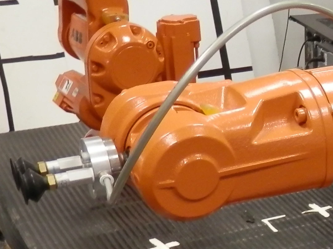
Cup spacing controls moment resistance. Hose bends, long tubes and small fittings slow evacuation and can snag or fatigue. Review the complete end-effector photograph or CAD with the part center of mass and robot approach direction overlaid.
Include acceleration, jerk and emergency stops
The retained load includes gravity plus inertial force from the commanded trajectory. Peak acceleration may occur during a short blend, direction reversal or protective stop rather than during steady travel. Payload mass uncertainty multiplies this error.
Measure actual tool acceleration and pressure during representative cycles. Derate commands when pressure margin is low, and do not assume the robot payload setting automatically proves part retention.
Calculate eccentric moment and peel risk
A center of mass offset produces a moment about the cup pattern. That moment redistributes normal load and can lift one lip even when the sum of nominal cup forces exceeds part weight. Flexible panels can bend and amplify the same effect.
Test every supported part orientation and pickup location. Record which cup loses contact first and whether the remaining circuit preserves enough margin for a controlled stop.
Treat pad deformation and wear as changing geometry
A compliant lip conforms to texture, but excessive compression can fold the cup, reduce effective area, slow release or create permanent set. Temperature, chemicals and repeated cycles change elastomer stiffness and friction.
Define inspection and replacement criteria from cracks, lip shape, evacuation time and pressure decay, not calendar age alone. Requalify after cup material, diameter, mounting height or spring compliance changes.
Separate low vacuum from abnormal pressure decay
A low initial vacuum can mean missed contact, an open cup or inadequate pump flow. A normal pickup followed by rapid decay suggests a growing leak, shifting part or damaged hose. Those cases need different retry and stop behavior.
Combine absolute pressure, rate of change, valve state and robot motion. Where available, flow or pump duty adds evidence. Apply timestamp discipline from the robot time-synchronization guide so a pressure drop is attributed to the correct motion event.
Make part-loss detection independent of one threshold
A single pressure switch may miss a slow loss that stays above threshold until a high-acceleration segment. It may also chatter near the limit. Use hysteresis, minimum dwell and motion-dependent limits with a documented maximum detection delay.
Cross-check pressure with gripper position, wrist force, motor current or vision when the risk justifies it. Redundant evidence must have different failure modes; two values derived from the same pressure sensor are not independent.
Watch energy, heat and continuous pump duty
A leaking system may maintain acceptable pressure by running the pump continuously. That hides the leak while increasing energy, heat, noise and component wear. Duty cycle is therefore a diagnostic signal, not merely an efficiency metric.
Log pump command, current, temperature and pressure across long production sequences. Define a degraded state before thermal protection or performance loss creates an unplanned drop.
Use a state machine from approach through release
Useful states include approach, contact, evacuation, verified hold, transport, degradation, controlled stop, release and confirmation. Each transition needs an event, timeout and safe destination. Repeated blind pickup attempts can damage the part or move it outside the expected pose.
Release also needs verification. Confirm pressure recovery or blow-off, part departure and a safe retreat before the tool leaves the drop zone. A stuck flexible part is a distinct failure from a dropped part.
| Test dimension | Levels to vary | Primary metric | Failure record |
|---|---|---|---|
| Part | Material, texture, warp, contamination | Pickup and hold rate | Seal pattern |
| Pose | Cup angle and pickup offset | Pressure margin | First lifted edge |
| Motion | Acceleration, jerk, stop | Peak decay and slip | Trajectory timestamp |
| Tool | New, worn and damaged cups | Evacuation time | Inspection result |
| Recovery | Leak and loss injection | Safe-stop success | Drop zone and response |
Release with an explicit acceptance checklist
Publish the supported part envelope, cup and hose configuration, pressure and decay limits, maximum evacuation time, motion limits, inspection interval and loss response. Keep pump firmware, valve logic and tool drawings under change control.
Close validation with the following checklist.
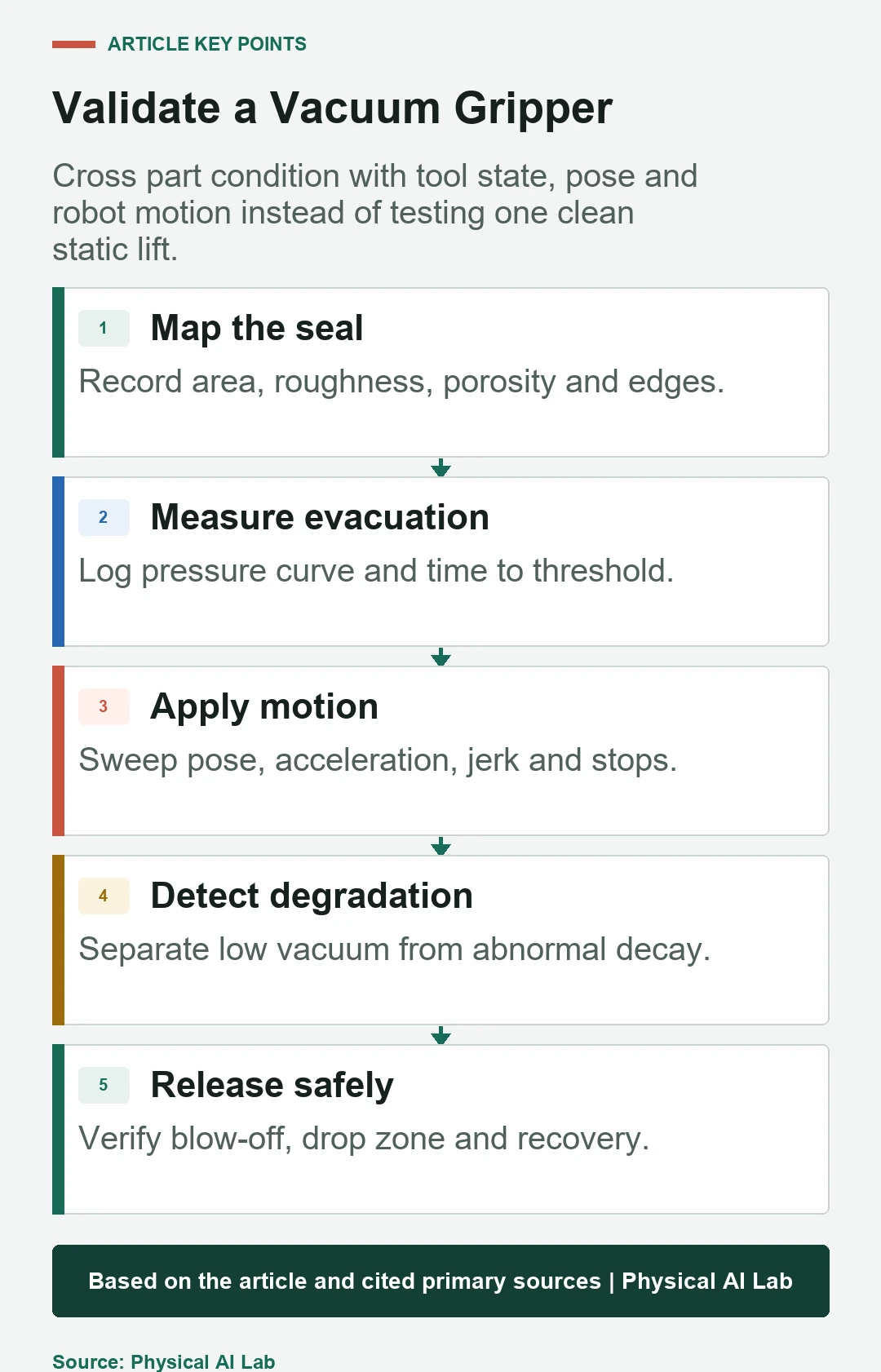
- Measure pressure at the installed tool under real flow.
- Cross surface condition with pose and motion.
- Include eccentric moment, stops and worst-case payload.
- Detect both failed pickup and degrading retention.
- Verify release, recovery and maintenance criteria.
Frequently asked questions
Does a higher vacuum always make the grasp safer?
No. Effective seal area, leakage, cup geometry, load direction and moment can dominate, and higher vacuum can deform fragile parts or cups.
Can a vacuum gripper handle porous material?
Sometimes, with enough flow and suitable cups, but through-material leakage must be measured across the actual part variation.
Are more suction cups always better?
No. More cups add area but also volume, fittings, alignment constraints and leak paths; circuit isolation and part geometry determine the benefit.
Is one pressure sensor enough for part-loss detection?
It can be adequate for a bounded application, but its delay and blind spots must be tested; higher-risk tasks may need independent evidence.
When should suction cups be replaced?
Use documented wear, evacuation-time and pressure-decay limits, plus chemical and temperature exposure, rather than visual age alone.
Retention Envelope and Safe Release Boundary
Vacuum retention is a tested operating envelope, not a pump specification. Keep people and damage-sensitive equipment outside the credible drop zone and follow the applicable machine risk assessment.